Connect Cables using connection parameters
The following text and screenshot images explain how to use the Connect Available Cable By Parameter options to connect cable media to ports.
 Select Ports for connectionIn order to connect the newly created Cable to the newly created patch panel, Ports on the selected equipment need to be chosen. This is done in the Ports and Connections tab in the Equipment Properties dialog, which displays a grid listing all Ports of the selected Equipment and the connected Cables and equipment.
This use case is intended to explain the use of different connection parameters (e.g., on Plug, Media, Port or device levels).
in this example the user has selected an 8 pin IDC port onto which cable media is to be terminated.
These Port entries have a Bare Copper Jack Type, which allows single Cable Media connections.
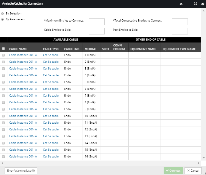
Clicking on the Connect Cables button opens the Available Cables for Connection dialog, as explained in the next point.
|
 Select "By Parameters" optionThe Available Cables for Connection dialog will only display the Cables whose endpoints currently exist near the equipment position and that have not yet been connected to any equipment. Since in the previous step multiple Ports have been selected, the radio button is pre-selected to the By Parameters value in the Available Cables for Connection dialog, placing the dialog in a batch connection mode. This also enables the four numeric input fields, which are explained in the following sub-topics.
|
PARAMETER OPTION
|
DESCRIPTION
|
|
Maximum Entries to Connect
|
The user cannot enter a value that exceeds the maximum number of connection points for the selected Equipment ports. In the above example, as the user only has single 8 pin IDC selected, then this number cannot exceed 8. If the user had 12 IDC ports selected, then the maximum number could not exceed 12x8 which is 96 conductors.
|
|
Total Consecutive Entries to Connect
|
This option specifies how many media entries to connect consecutively before applying either of the skip parameters. If the user wanted to connect the first 8 cable media entries consecutively, then they would enter 8. If they had 12 IDC ports connected and wanted to terminate all 96 cable conductors sequentially then they would also enter 96 in this field. However, lets say they only wanted to connect the first 2 conductors of the cable before skipping pins in the connector, they would enter 2, this would then connect 2 consecutive media entries in the Cable list before applying any of the Skip options.
|
|
Cable Entries to Skip
|
When left empty cable entries are connected consecutively however, if the user specified 1 and selected the first cable entry in the grid above, it will only connect every other cable media, i.e. 1, 3, 5 & 7.
If total consecutive entries was set to 2 and this option was also set to 2, then it would connect conductor 1 and 2 to pins 1 and 2, then skip the next two conductors before connecting conductors 5 and 6 to pins 3 and 4.
|
|
Port Entries to Skip
|
when empty ports are connected consecutively however,
if the user specified 1 and left Cable Entries to skip blank, then the cable media would be connected as follows:
Conductor 1 to Pin 1, Conductor 2 to Pin 3, Conductor 3 to Pin 5, Conductor 4 to Pin 7.
if the user specified 1 and set Cable Entries to skip = 1, then the cable media would be connected as follows:
Conductor 1 to Pin 1, Conductor 3 to Pin 3, Conductor 5 to Pin 5, Conductor 7 to Pin 7.
|
Using the connect parameters is a a very powerful option and is useful when needing to terminate bulk cabling or when required to make more complex types of wiring connections, primarily associated with copper wiring for voice, radio or alarms systems..
|
|