4.3.9.1. Inserting Maintenance Holes
Maintenance Hole creation starts with opening the desired Area in Design World. This automatically enables the Toolbox on the left, where a designated button for Maintenance Hole creation is located:
Click on it opens a separate dialog organized into two tabs. The first one - General, similarly to standard General tab, allows specifying some basic Maintenance Hole properties, such as Name and dimensions:
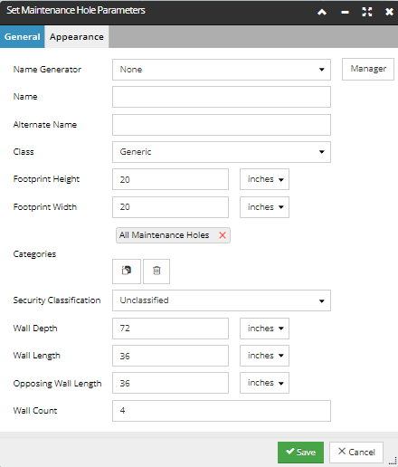
The first set of Maintenance Hole properties that need to be specified upon creation are Name and Alternate Name. These can be either manually specified, or automatically generated from an existing Name Generator for Maintenance Hole Super Category. Conveniently, the user an enter Name Generator Manager from here and specify a new one, if needed.
Note: The rest of the properties are predefined with default values, but can be changed later on.
Most of the Maintenance Hole properties are self-explanatory, except for a few following below:
-
Class, which can be selected from a list, where Tube Box, or Man Hole types can be selected, aside from the default generic type.
-
Opposing Wall Length, which allows the user to specify non-square rectangle (4-wall) Maintenance Holes.
The second tab - Appearance tab, allows the user to specify the footprint icon shown in Design World:
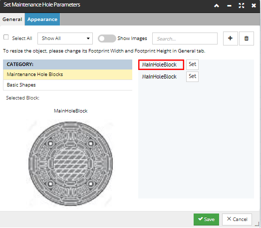
From here, the user is able to
-
select footprint icon from a list of uploaded icons to assign to the new Maintenance Hole object
-
upload a new footprint image
-
preview the final
Finally, changes are saved by clicking on the Save button, or discarded by clicking on the Cancel button. Also, this dialog enables direct access to the Butterfly Diagram dialog via a button at the bottom of the dialog.