4.3.15.1. Multi-Area cabling
One of IRM's advanced features is Multi-Area cabling. IRM enables a single Cable to be routed across multiple Areas using the Continue in Area... option on the Cable's context menu. This section covers a use case for routing a Cable over multiple Areas.
To review, an Area is a unit of design in IRM where objects occupy some region in a 2D (x,y) plane. Typical Areas include a floor in a building or the ground level of a multi-building campus. A Site can support an arbitrary number of Areas. For drawing purposes, Areas can be shown in a Design World panel (usually only one or two Areas within the same panel for example the floor of a building with or without the surrounding grounds/outside plant region).
Note: It is important to ensure all Areas within which the Cable is to be routed are opened prior to inserting the Cable. This is necessary, as it is not possible to open Areas during the Cable insert process. Open the appropriate Areas by selecting the Open option form their context menu in the Categories & Types tree.
The following screenshot(s) and text explain a simple use case scenario:
-
selecting a Cable from a predefined set of Cables
-
inserting a Cable in Design World
-
continuing the Cable's route in another Area

Select Cable instance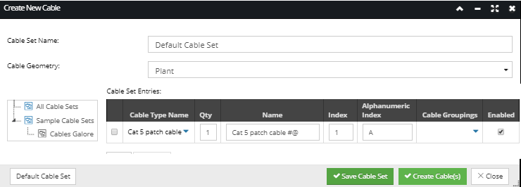 Select Cable instance from the Default Cable Set predefined and enabled by default for selection when the Create New Cable dialog is opened. In this example the Default Cable Set consists of a single Cat 5 Patch Cable instance, which is Enabled by default and is ready for insertion into the Design World. Clicking on the Create Cable(s) button automatically closes the Create New Cable dialog and sets the focus to the Design World in Cable drawing mode.
For more details about inserting Cables into the Design World and Cable design and management in general, click on the following topic and its subtopics - Cable Management.
|
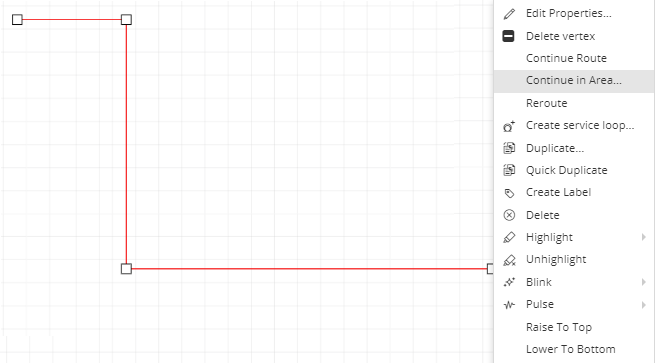
Select Area to continue Cable route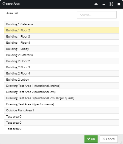 This dialog displays a list of all Areas available for Cable routing continuation. The list can be filtered by entering search criteria in the the Quick Search field. To continue the cable route into the selected area, select the appropriate Area row entry and then click on the OK button. This dialog will be closed and brings focus to the selected Area in the Design World with the mouse cursor in Cable routing mode
|
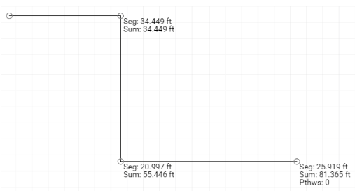
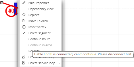
Continue the Cable routing in the other Area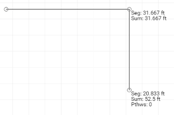 A single left click on the canvas (drawing area) creates the first point in this new section of the Cable's route, indicated by a hollow circle icon. The cursor coordinates and length of the Cable route are displayed at the end of each cable segment within the Cable route. Double clicking sets the final point of the Cable (displayed in the first screenshot in the next step).
|
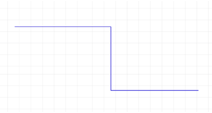
View newly created Cable in both Areas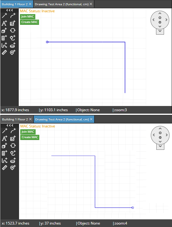 After Cable drawing is completed in the other Area, the final Cable is displayed in default layout mode, with the addition of a Cable continuation icon (small hollow circle) added at the appropriate end of each Cable segment in each Area, as displayed in the images above.
|