Path Tracing Snipped/spliced Cables
One significant feature of IRM Circuit Path Tracing is its support for spliced Cables. The following is a demonstration of this feature through an example in the IRM Design World, as shown in the screenshot below:
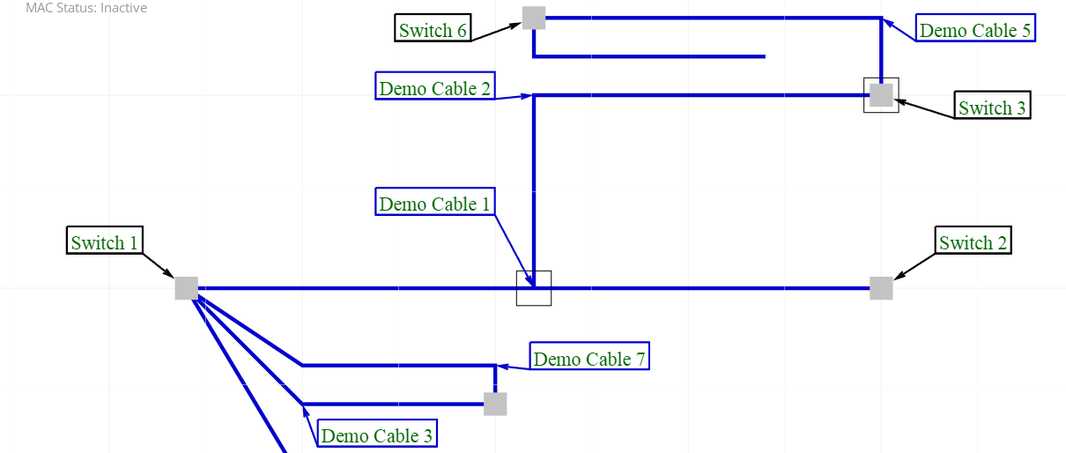
The following are some properties of this example which are relevant for this topic:
-
Multiple cables have snipped media and/or media spliced together via a coupler
-
Cables are routed through multiple Equipment instances.
Let's assume the user wants to trace a path on a Circuit, starting from Switch 1 shown in the image above. In this case, keeping in mind there are spliced Cables connected to this Equipment instance, it is very important to have full information about the physical path of the circuit.
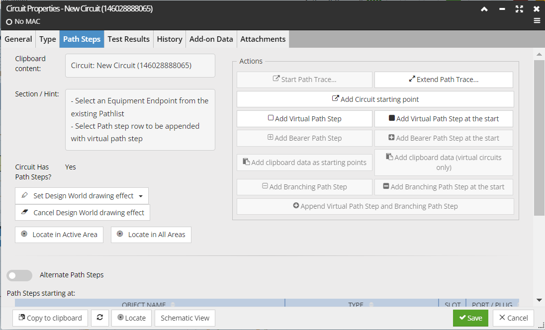
The path tracing operation is started by clicking on the Start Path Trace button inside the Path Steps tab in the Circuit Properties dialog. This generates a Path Step sequence. Each Path Step in the sequence represents a single point-to-point link in the Circuit.
In a path trace operation as we are presently discussing, all of the Path Steps will be physical Path Steps -- that is, they indicate a specific Port (or even specific connection points in a Port) and Cable Plug. However, it should be noted that IRM Circuits can also contain virtual Path Steps, though the latter will never be generated by a path trace operation. A virtual Path Step indicates a device or location that the Circuit goes through without consideration of the exact details -- it is more abstract.
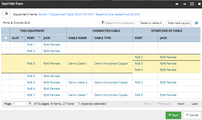
Paste the desired Equipment instance from the Clipboard as the starting point of the Path Trace:

This new Circuit's path starts at a selected Port of the selected Equipment "Switch 1" and continues along a sequence of the "Demo Cable 1" Cable:
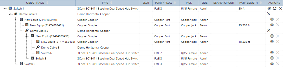
The following is the full Path Steps grid - notice there are multiple types of objects and multiple branching Path Steps that have been traced:
-
This path step sequence is displayed as child / branching sequence and is followed by a Branching Path Step with different Ports in each of its child path Steps. The number of Path Step Sequences in the Branching Path Step depends on the number of Cables spliced to plus one extra for un-snipped media that are connected at the far end. In this example Demo Cable 1 has some media spliced to Demo Cable 2 while some non-snipped media continue to Switch 2, that is why there are 2 Sequences directly under Demo Cable 1.
-
a Coupler identies a location where a cable has been snipped or spliced to another cable. That is, two physical Path Steps are added for the Coupler - the first with null Plugs (which represents the internal linking and has a path length of 0) and the second with the coupler’s outgoing Plug (which represents the spliced-in Cable, with a non-0 path length).
-
These rules apply for spliced Cables recursively and another Branching Path Step is added within the appropriate Path Step Sequence (for Demo Cable 2 in this example). In this way, there can be arbitrary levels of branching in the path trace.