4.3.10. Pathway Management
The Pathway object in IRM is used to define a known pathway between two locations. It can be used to define Outside Plant ductbanks or cable tray systems required to support the installed cable infrastructure. Pathways are used to define ducts, cable trays, trunking or any type of pre-determined route over which cables are routed.
Some examples of different usages of Pathway objects in IRM, displayed in the following screenshots:
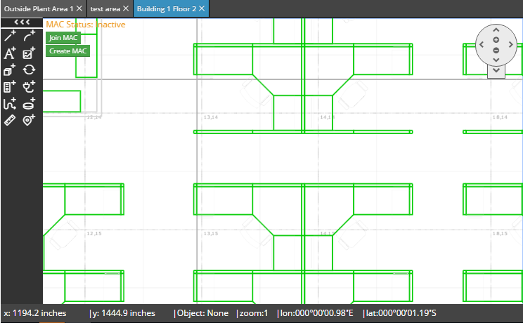
In floorplans - Pathway route representing duct or cable tray used to route cables into or between Telecom Room spaces.
-
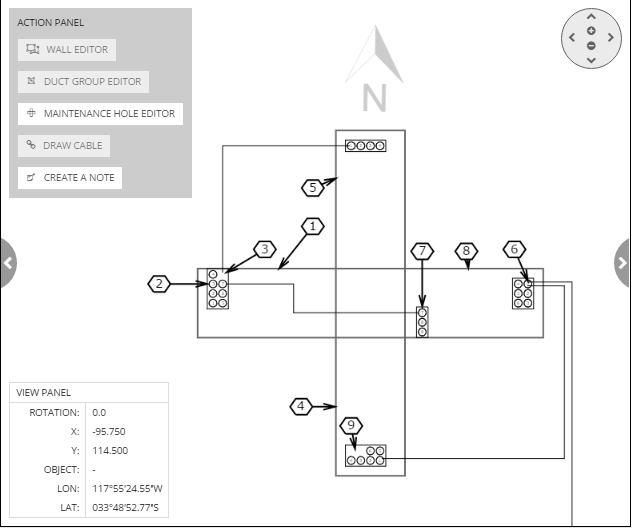
in the Butterfly Diagram - ducts representing the endpoints of a routed duct within a duct group on a Maintenance Hole Wall.
-
in Datacenters - Pathway routes representing suspended and floor mounted tray systems between racks
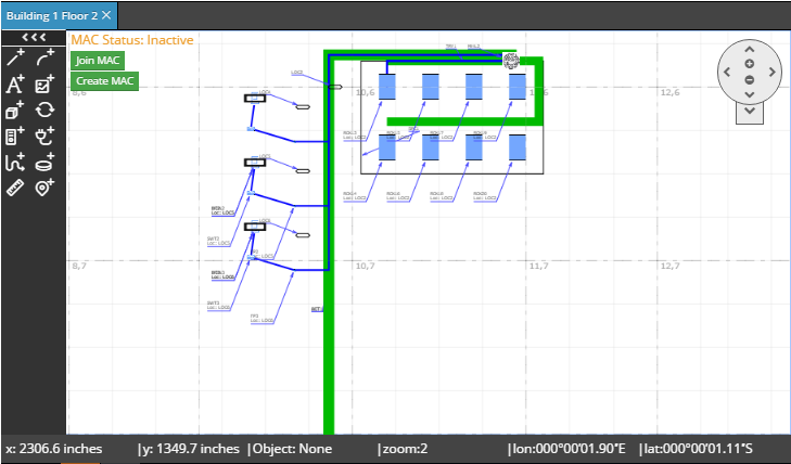
-
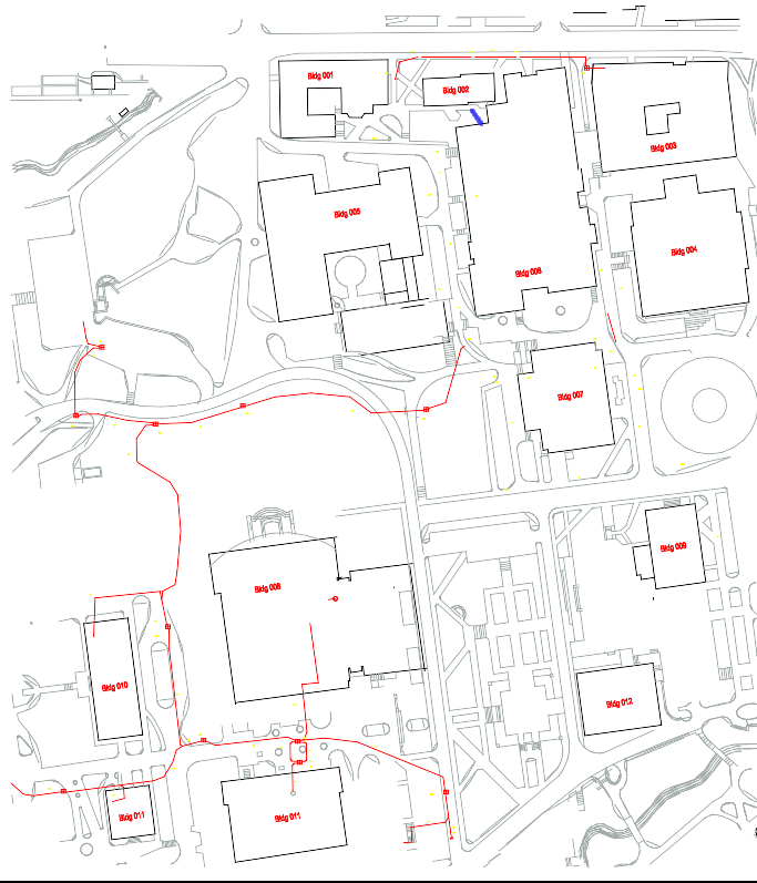
in Site plans - Pathway routes representing ducts between building entrance facilities and maintenance holes
In most cases, Pathways in IRM are used to describe the spaces within which cables are routed and are used to define and describe the installed conduit, tray and duct routes. Pathway objects are visually represented similarly to Cables, but usually with thicker lines, and can be managed in the Design World.
Importantly, the route of a single Pathway is linear, that is, there are no side branches or forking within a single Pathway. However, individual Pathways can be connected to each other at their endpoints, or in the case of Trays, at arbitrary points, which allows more complex structures to be built.
In the following sub-topics several features concerning Pathway management in Design World will be covered:
-
Pathway hierarchies
-
Inserting new pathways
-
Routing pathways
-
Routing cable over pathways
Another place in IRM where Pathway objects can be managed through graphical representations is within the Butterfly Diagram. For more details click on the following link - Using the central Butterfly panel.
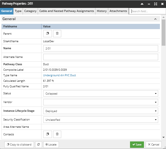
Similarly to other managed objects, Pathway objects are accessible from several places in the application: the Pathways tab in the Object Grid, the Pathways section in the C&T tree and directly in the Design World. Each of these places in the application enable opening the Pathway Properties dialog, available as an option from the context menu. This dialog is a standard Properties dialog containing several standard and object specific tabs.
Some specific, key fields in the General tab of the Pathway Properties dialog are discussed next:
-
General group :
-
Pathway Class - IRM defines 3 Pathway classes : Duct, Tray, Ladder and Lane. Note that this is not the same as a Pathway's Type or Category; the Pathway Class is used to determine some rules (i.e., business logic) for how the Pathway can be manipulated. For example, a Duct Pathway can only have Cables enter and exit at each end, while a Tray Pathway allows Cables to enter and exit anywhere along the route.
-
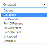
Status - this is an additional property that defines a Pathway status in respect to it's availability for adding child elements like Cables or Pathways. Available values are:
|
IMPORTANT
For now, a decision has been made that special support for Riser Pathways (Ladder) will wait and that for the current release, risers will be handled using the "stub Pathway" approach. However, we do have the Ladder Pathway Class in the software, and we want to keep that so that ladders in riser areas can be accurately classified as Ladders.
It is also possible, though certainly less common, to use ladders instead of Trays in equipment rooms. Therefore, for now, we simply want to treat Ladders exactly like we treat Trays – just essentially make the Ladder Pathway Class an alias for Tray.
|
-
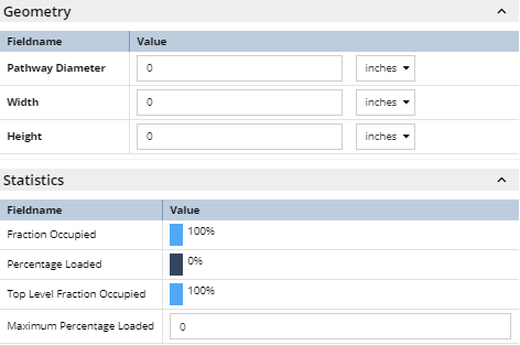
Geometry and Statistics groups:
-
Pathway Diameter, Width and Height are properties which values are used for calculating values shown in the Statistics section below.
-
Statistics group displays the following calculated properties, which indicate how full the pathway is.
-
Fraction Occupied - indicates the amount of free space including any free space in child Pathways,
-
Percentage Loaded
-
Top Level Fraction Occupied - indicates the amount of free space only in the top-level (parent) Pathway, assuming the child Pathways are fully occupied, whether they actually are or aren't.
-
the additional Maximum Percentage Loaded property, which can be specified by the user as a threshold value, so when someone tries to add a Cable or inner duct such that this value would be exceeded, the application performs a validation check, exactly like the one used for the three values above.
-
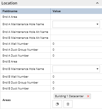
Location group is mostly consisted of derived (calculated, read only) property values, except for the following fields, which are specified by the user:
-
Maintenance Hole at End A, Maintenance Hole at End B - are references to the Maintenance Holes located at End A and End B of the Pathway object.
-
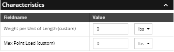
Characteristics group, which contains properties that can be specified by the user:
-
The idea is that every inner duct and cable placed in a Pathway contributes a known amount of weight per linear foot/meter, calculated from the values specified for the Cable Type as weight Per Length property for the Pathway Type as weight Per Length property. Because the installation of many Pathway objects is custom/ad hoc in one way or another, the Weight Per Unit of Length property displayed here for the Pathway object can be specified by the user, along with the unit. This value says how much weight a Pathway can support per foot/meter. This parameter for Pathway Type is an intrinsic property of a Pathway instance, while the custom/override parameter in Pathway instance (shown here) captures installation-related limitations.
-
The final part of this feature is the utilization of the Pathway from a loading perspective, given by Pathway's loading Utilization, which is calculated by simply loading Per Length / max Loading Per Length, the user can set a threshold value for this field via the Pathway Max Point Load property. When the user tries to add a Cable or inner duct such that max Loading Utilization would be exceeded, the application performs a check, exactly like the one used to determine if fraction Occupied would be exceeded. Note that this value should always be less than or equal to the corresponding Type's max Loading Per Length value.
-
While the design applies to all Pathway objects, in practice the concept of pathway weight is calculated only for trays, ladders, and any other pathways that are suspended from the ceiling or in risers.
Another specific set of properties is located in the Cable and Nested Pathway Assignments tab, which is covered in more detail in the Pathway hierarchies sub-topic.