Port Visualization
Besides showing the arrangement of Equipment in a rack, chassis, or wallboard, another important purpose of the Elevation dialog is to visually show the status of each port, as defined by the value of Equipment Port State field.
The Port State is depicted by decorating an equipments port with small icons drawn at the location of each port on the containing equipment.
An unoccupied state (nothing plugged in) represents the “available” status and is depicted in white. For all other states, a small colored rectangular icon is overlayed onto the relevant port. For some states a text moniker is overlayed on the colored port state to help further identify the port state.
An unoccupied state (nothing plugged in) represents the “available” status and is depicted in white. For all other states, a small colored rectangular icon is overlayed onto the relevant port. For some states a text moniker is overlayed on the colored port state to help further identify the port state.
There are two varieties of Port State
-
one designed for administrative purposes -- that is, whether a cable is physically connected or not
-
another designed to reflect the operational state -- that is, whether the port is functional, broken, on a circuit, etc.
Administrative Port States
-
Available
-
In Use
-
Reserved
Operational Port States
-
Functional
-
Broken
-
Intermittent
-
Disabled
-
Reserved
-
On Circuit
Note that there are two separate concepts of "Reserved", one at the Admin level and a second at the Operational level. An Administrative Reserved port state is set by connecting a cable to it whilst recording MAC operations whereas, a Reserved in operational state is driven directly by SNMP Port States from a 3rd Party discovery / NMS systems .
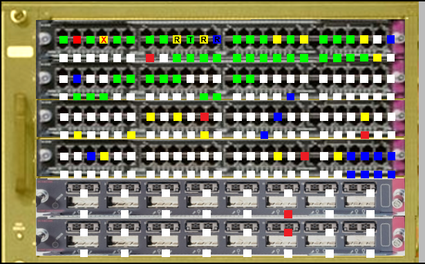
The following screenshot is an example of the (Equipment) Elevation dialog showing a front facing Equipment displaying different Port States - notice the differently colored icons and different symbols overlayed on top of specific Ports. The meaning of each symbol and color is shown in the Port Visualization Key in the lower-right portion of the dialog and explained further below.
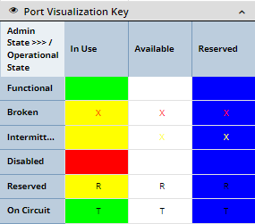
The Port Visualization Key accordion section on the bottom-right shows the configured visualizations for the various port states in a table with each row corresponding to an Operational Port State and each column to an Admin Port State. Cells that correspond to meaningless/illegal combination are left blank.
The visualization colors can be configured by Admin users in a separate section of the Global Settings dialog:
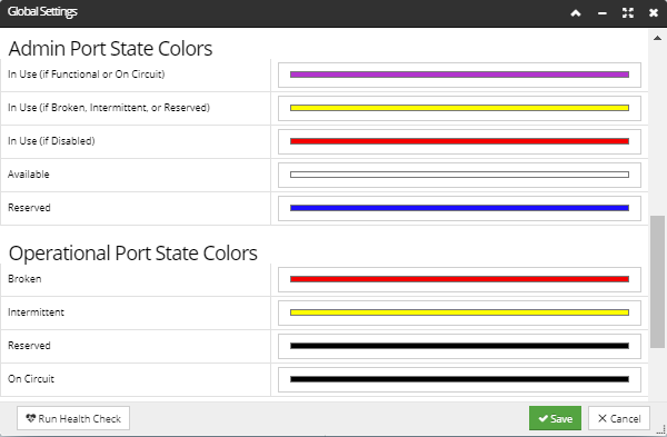
While the colors can be chosen, the symbols/shapes are fixed.
The user can set the port state manually, but in some cases the value is changed automatically:
-
When a Plug is plugged into a Port, Admin Port State auto-transitions to In Use
-
When a Plug is removed from a Port and Admin Port State was In Use, it auto-transitions to Available
-
When a Port is added to a Circuit (via a Basic Path Step containing the Port), Operational Port State auto-transitions to On Circuit
-
When a Port is removed from a Circuit and Operational Port State was On Circuit, it auto-transitions to FunctionalNote: Any Admin or Operational state can be manually set at any time; by doing so does not prevent future auto-transitions, except that it may prevent the necessary pre-conditions from being met. For example, if an Operational Port State is set to Broken for a Port on a Circuit and the Port is subsequently removed from the Circuit, Operational Port State is not auto-updated due to the pre-condition of the 4th rule above