4.3.8. Power management
This section provides basic information about how equipment power usage is modeled in IRM, with additional focus on power metrics and overload conditions.
Below is a typical diagram of a simple power circuit managed in in IRM:
Below is a typical diagram of a simple power circuit managed in in IRM:
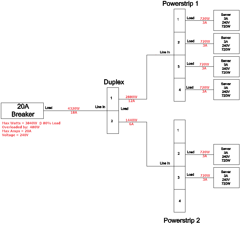
The diagram shows a typical example of the power circuit management capabilities within IRM. It is possible to see the powerloading at each equipment in the power circuit by viewing the Environmental properties of the relevant equipment.
For Example:
if the user viewed the Environmental properties of Powerstrip 1, they would see the Nominal Watts value of 2880W which is sum load of the 4 connected servers.
These values are dynamic and re-calculated whenever equipment is connected or disconnected form the powerstrip
For Example:
if the user viewed the Environmental properties of Powerstrip 1, they would see the Nominal Watts value of 2880W which is sum load of the 4 connected servers.
These values are dynamic and re-calculated whenever equipment is connected or disconnected form the powerstrip
The 20A breaker in the above diagram is the Equipment Type that is defining the capacity of the entire circuit, it supports limiting the circuit capacity by setting:
-
the Maximum Watts Supplied property to manage the total Watts allowed on the circuit.
-
the Maximum Amps supported by the Load side port when building the power circuit.These two values are checked whenever an equipment is removed or added at any point along the circuit to determine if the circuit is being designed within the applied constraints or has been overloaded.
When a circuit becomes overloaded, a warning message is displayed informing the user that the the circuit capacity is exceeded.
In the above example, we can also see that the breaker Max Load in Watts should not 3840W @ 80% of the breaker capacity, yet the current designed loading is showing that the circuit has the maximum running load of 4320W causing a circuit overload of 480W.