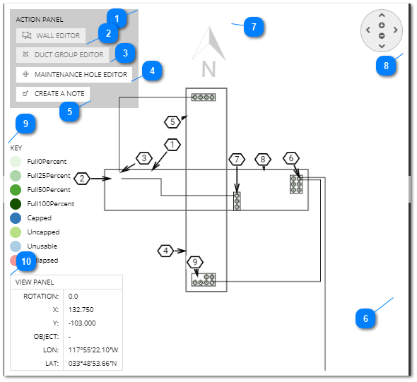
Using the central Butterfly panel
This section describes the following actions enabled by the central panel in the Butterfly Diagram:
-
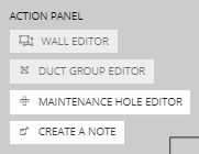
Wall selection and modification
-
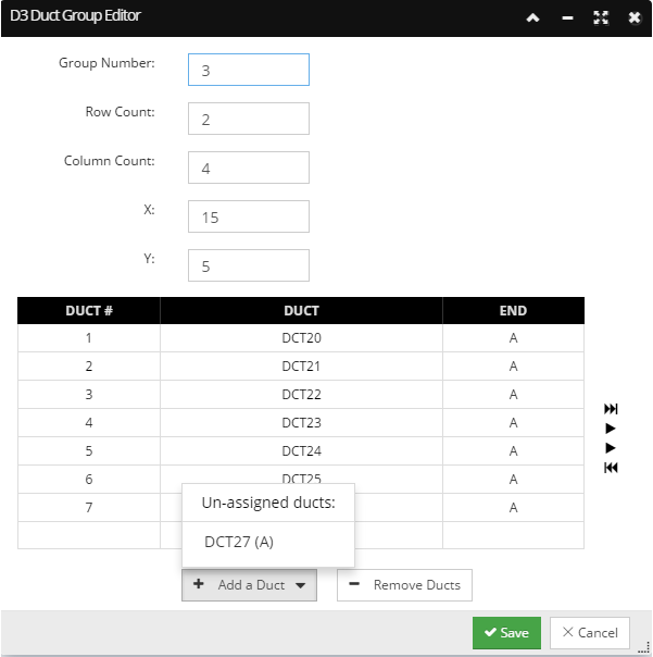
Duct Group selection, creation and modification
-
Duct selection, creation, removal and modification
-
Cable selection and drawing
-
Note selection and creation
-
Additional convenience controls like Pan / Zoom, View Panel, and Geo ControlThe following is a breakdown of its main features:
'Wall Editor' Action Panel button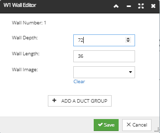 Also, the editor enables assigning an attached image to a Wall simply by selecting the appropriate image name from the drop down menu. The same image is displayed in the Wall Image Gallery (right panel) and gets selected (highlighted) when the corresponding Wall gets selected (in the Nested Pathway and Cables tree, or in the central Butterfly diagram).
Note: Before assigning an image to a Duct Wall, it should first be added to the Attachments tab in the Maintenance Hole Properties dialog. Click on the following link for more information about Attachments.
The Wall Editor also contains the Add a Duct Group button, enabled only upon Wall selection. Click on this button opens an empty Duct Group Editor dialog, explained more in the next point.
|
"Create Note" action buttonClick on the Create Note button creates and automatically selects an empty note and adds a marker for it in the central drawing.
The note marker can be moved around in the diagram to the desired position.
A new row entry with default "New Note" text is created at the bottom of the grid, highlighted and automatically consecutively enumerated.
|
Central drawing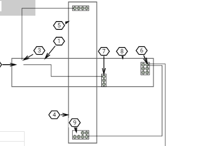 The central rectangle in the butterfly drawing is an equilateral polygon with multiple rectangles on the sides, drawn in alignment with each of the side of the central rectangle (i.e., hole). Each element from the drawing, except for the central rectangle, is selectable and accordingly highlighted when selected in either this central or the left side panel.
|
Geo control This control indicates the angle of North that is set for the drawing. Note that click and drag on the control changes the value of the Angle of North field value in the Maintenance Hole Properties - General tab dialog, which means the Maintenance Hole is rotated so that the Geo Control is pointed North.
|
Pan / Zoom control This is a standard Pan / Zoom control, similar as the one in Google Maps and the same as in the Design World. Click on up / down / left / right arrow buttons moves the central drawing in the selected direction. This can also be done by drag and click anywhere in the central drawing. Click on the + / - buttons zooms the drawing in / out. This can also be done by spinning the mouse wheel while the pointer is anywhere in the central drawing.
|
Duct usage analytics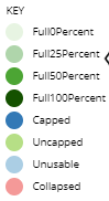 The color legend shows Duct usage within the Butterfly Diagram, without the user having to search for that property manually for each Duct. Another feature is that the color coding of each Duct status inside the Butterfly Wall automatically changes to show when the fill ratio reaches thresholds.
The following Duct usage thresholds are defined using shades of green as color:
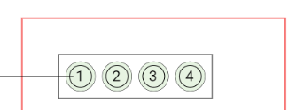
The example from the screenshot below displays a Wall inside the Butterfly Diagram with 4 Ducts assigned and completely empty, that is, 0% full, as indicated by the lightest shade of green coloring:
 In addition to the basic statuses listed above, the following are also defined:
The following activities can cause the Pathway status to automatically transition between different values:
In addition to this Duct usage analytics, the Pathway hierarchies shows the percentage usage for each top-level Duct.
|
View Panel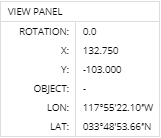 The left side of this panel is always fixed, while the right side dynamically displays different values depending on the position of mouse pointer (very similar to the toolbar at the bottom of the Design World). In this example, the Wall is selected, which is also corresponds to the Object value visible in this panel.
|