WiFi coverage visualizations
The IRM Design World allows the user to visualize WiFi coverage and other kinds of physical infrastructure coverage such as air conditioners, sprinklers, sensors, alarms, etc. To support this feature, IRM v1.5 introduces the following two types of objects - Coverage and, in support of it, Standards.
Within the IRM environment, these objects are used as follows:
-
An Equipment Type can support none, a single, or multiple Coverage objects. As for the associated Equipment instances, even though supporting more than one Coverage is useful in some cases, like for WiFi routers that have different power modes, or which support more than one standard, IRM makes an assumption that a given Equipment instance will only use at most one Coverage. An Equipment instance defaults to supporting whatever Coverage is first assigned to the related Equipment Type. In case the related Equipment Type doesn't support any Coverages, its instance will also have no default Coverage object assigned. However, IRM users can select a Coverage to use for any given Equipment instance, regardless of whether it had a default one set.
-
Standard objects represent real-world standards. For example, for WiFi there is the 802.11 series, like 802.11n or 802.11ac. This information includes two nominal ranges:
-
If only a single range is available, both can be set to the same value, or one of the ranges can be set to 0.
-
If neither of the ranges is available, both fields can be set to 0.
The following are basic features of the user interface aspects of the WiFi Coverage visualization.
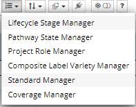
The Standard and Coverage Managers are accessed from the Extendable Enumerations menu from the Function bar in the main application screen:
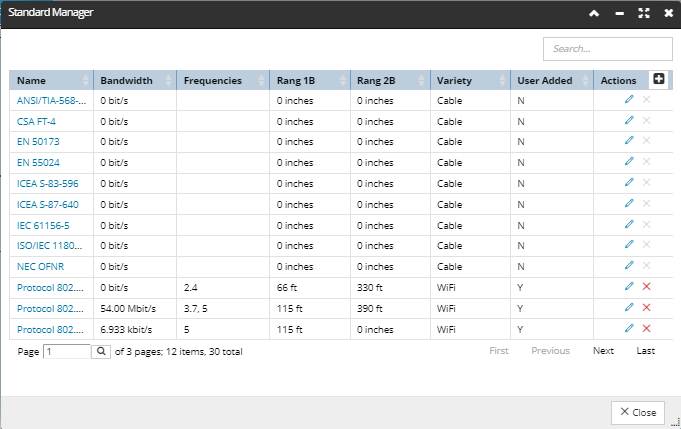
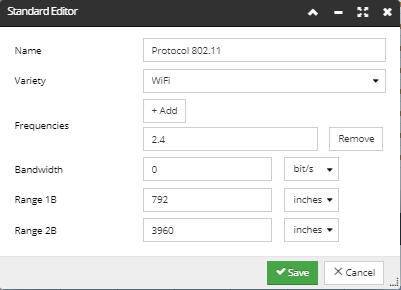
The Standard Manager dialog and associated Standard Editor dialog are not much different from other Manager-type and Editor-type dialogs used throughout IRM, in terms of the layout and the way the data is displayed and edited. The data grid in the Standard Manager lists all Standard objects by their name, along with their basic properties, such as the associated Bandwidth and Frequencies, if it's a Cable or WiFi Variety, and similar. They can be viewed in more detail and edited via the Standard Editor dialog, simply by clicking on the relevant "pencil" Action button from the Manager dialog:
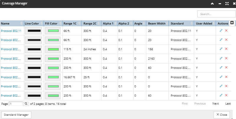
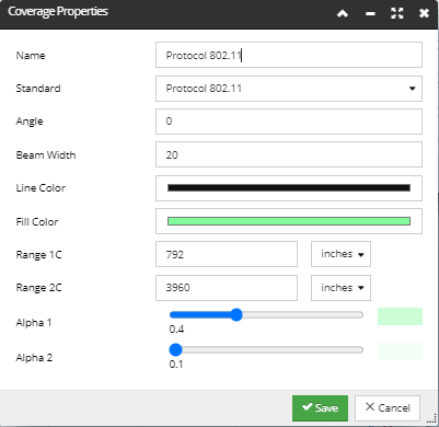
The Coverage Manager and the associated Coverage Properties dialogs are similar to their Standard counterparts. The Coverage Manager lists all Coverages by their name, along with their basic properties and drawing properties, which define how a specific Coverage is represented in the Design World. These can be viewed in more detail and edited for each Coverage object via the associated Coverage Properties dialog, simply by clicking on the "pencil" Action button for the related data grid row inside the Manager dialog. In addition, the Standard Manager can be accessed independently from here by clicking on the button on the bottom of the dialog:
There are other places in the application from which certain aspects of Standards and Coverages are managed:
-
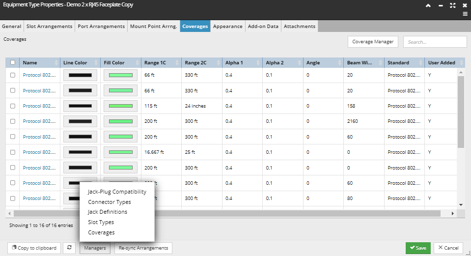
inside the Equipment Type Properties dialog there is a separate tab for Coverages, displaying the same data as the Coverage Manager dialog and allowing the user to select which Coverages apply to this Types. There are no Action buttons in this tab, only a button link to the Coverage Manager dialog, where Coverages can be created, edited, or removed. In addition, there is another way to access the Coverage Manager from any tab in the Equipment Type Properties dialog - from the Managers menu on the bottom of the dialog:
-
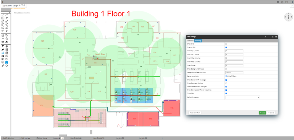
Inside the Drawing tab of the User Settings dialog there are several properties for showing or hiding Coverages in the Design World:
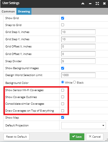
Wifi Coverage Visualization Types
Show Wi-Fi Coverages
Show Wi-Fi Coverages include Coverage Outlines
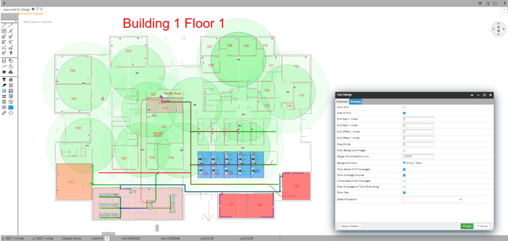
Show Wi-Fi Coverages include Consolidated similar coverages
In addition to the general support described above, there are additional specific caveats and rules that apply to how Coverages are rendered in the Design World:
-
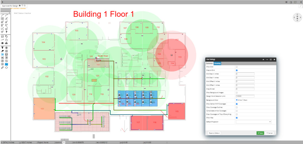
A Coverage object is rendered along with it's associate Equipment object. Therefore, if the "Coverage" User Setting is enabled and the Equipment itself is visible in the Layer Manager sense, the Coverage will be rendered, otherwise the Coverage will not be rendered.
! IMPORTANT ! - Given that IRM allows the users to have overlapping Coverages of different Standard Varieties - be aware that IRM also allows use of existing Layer Manager tools to make the Equipment invisible, which may prevent the Coverage from being drawn.
-
Note also that there can be cases like a rack-mounted WiFi router where the router itself does not get drawn because it’s in the Rack, but the Coverage is still drawn.