4.3.10.1. Defining new Pathway Types
While the IRM Pathway Library contains a large number of commonly used Pathway Types, occasionally a customer will have a type of Pathway that is not in the Library.
In this case, in order to best manage those Pathway instances in IRM, it is necessary to create a new Pathway Type.
To define a new Pathway Type, follow these steps:
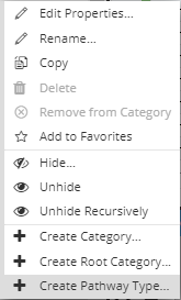
 Select "Create Pathway Type..." optionSelect the Category within which the new Pathway Type is to be defined. Open the context menu on the selected Category and select + Create Pathway Type... from the context menu. This opens a new instance of the Pathway Type Properties dialog with default values set to some of the fields, while others are left blank.
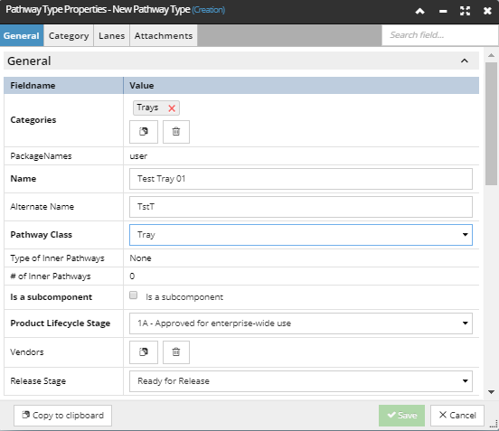
The Pathway Type Properties dialog contains the following tabs:
-
-
-
Lanes (only for Trays and Ladders) -
|
 Configure the necessary fields in the "General" UI group in the "General" tab The General tab is opened by default and is the only tab that requires several mandatory fields to be set before the newly created Pathway Type can be saved. Mandatory field names are displayed in bold text. A specified number of a single type of child Pathways can be added to a Pathway Type.
When a Pathway instance is created from this Pathway Type, the system will automatically create and name the children according to the parameters specified in this dialog.
In case of Duct pathways:
-
Type of Inner Pathways - the Type of the child Pathway instance(s)
-
# of Inner Pathways - the number of child Pathway instance(s).
In case of Trays/Ladders, child Pathways are specified in the Lanes tab, which is explained in more detail in the next topic - Tray Pathway Lanes.
Note: The total cross-sectional area of child pathways cannot exceed the maximum Utilization value of the parent Pathway (maximum Utilization field is explained further in step 4).
|
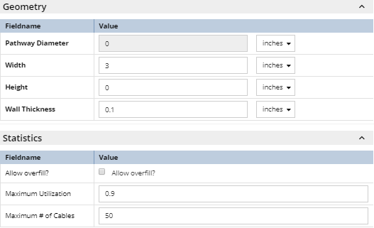
 Configure the necessary fields in the "Geometry" and the "Statistics" UI groups in the "General" tabDepending on the Pathway Class, either diameter or width and height are used to calculate the parent Pathway cross-sectional area, and from that, the utilization. Diameter is used for Duct Pathway Class objects, while Height and Width are used for Tray or Ladder Pathway class objects. Utilization is calculated based on the either Diameter (i.e., pi * (d/ 2)^2) or Width x Height (w * h)) and is updated accordingly in the dialog when these values are changed.
Wall Thickness is used for inner ducts to calculate how much space they consume. An inner duct, even if empty, consumes some space and even with no cables, a Pathway will have some of its cross-sectional area consumed by inner ducts, according to the following formula:
cross-sectional area = pi * (Diameter / 2) ^2 - pi * ((Diameter / 2) - wallThickness) ^ 2
The cross-sectional-area values for all inner ducts must be subtracted from the parent duct's cross-sectional-area when fraction Occupied is being computed.
Statistics group contains the following properties:
-
Allow overfill? is a Boolean field and applies only to Tray and Ladder Pathway Class objects. Setting this field to true by clicking on the checkbox enables the user to exceed the Maximum Utilization and/or Maximum Cable Count -- it is the software equivalent of allowing some extra cables to be added to the Pathway beyond its rated limit.
-
Maximum Utilization refers only to the top level parent Pathway utilization. This value can be set to a decimal value from 0 to 1, which when multiplied by 100 represents the percentage of the Pathway that is filled with Cables and/or child Pathways. This value defaults to 1, which means the parent Pathway can be 100% filled. For ducts in particular, it is more realistic to set the maximum utilization to a number like 0.8 that allows a small amount of leftover space in the duct.
-
Maximum # of Cables specifies the maximum number of Cables that can be added / assigned to an object of this Pathway Type. This value is set to 0 by default, which means there is no restriction on the number of Cables.
NOTE: Unless Allow overfill? is set, IRM will enforce both Maximum Utilization and Maximum # of Cables; that is, whichever is more restrictive will be the effective limit as to what can be placed in the pathway.
|
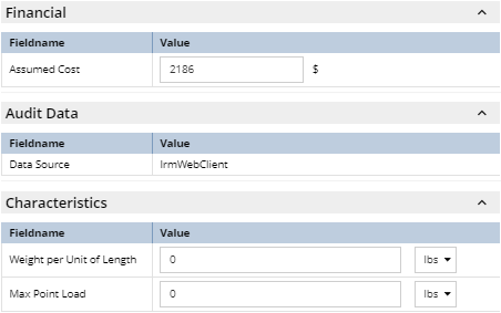
 Configure the necessary fields in the remaining UI groups in the "General" tab
Additional utilization properties can be specified under the Characteristics UI group and their main purpose is to show the total weight for the cables calculated by the number of feet the cable is in the pathway multiplied by the per foot attribute of the cable type. This result can then be shown as a percentage of max load on the pathways properties.
|
 Save the newly created Pathway Type objectOnce the new data is entered it can be saved by click on the Save button, which closes the Pathway Type Properties dialog and displays the new Pathway Type object in the C&T Tree. To cancel Pathway Type creation, click the Cancel button, which will close the Pathway Type Properties dialog and bring focus back to the main application screen.
|
|