4.3.10.2. Tray Pathway Lanes
In IRM, Tray Pathways support a special, optional feature known as Lanes. The feature is meant to model physical Trays that have thin dividers running along their length internally, which partition the tray into "lanes", "sections" or "partitions". Such dividers can be part of the Tray when it's purchased, or added on during installation of the tray. IRM supports both use cases.
In IRM, a Lane occupies part of the space inside a Tray in much the same way that an inner Duct occupies space inside a Duct. In fact, under the hood in IRM a Lane is actually a separate Pathway object, again much like an inner Duct.
Note, however, that unlike an inner Duct, a Lane does not intrinsically occupy any cross-sectional area itself (the dividers are assumed to be quite thin), it only contains a cross-sectional Area. Therefore, adding Lanes does not reduce the total available cross-sectional Area for Cables, it just splits it up into parts.
For the most part, the user does not have to care that Lanes are separate objects, because IRM provides a special, convenient user interface for adding Lanes to both Pathway Types and to Pathway instance objects. That is, the user does not have to create Lane Pathways explicitly, they just have to indicate how the space in a Tray is divided into Lanes. This user interface is described below.
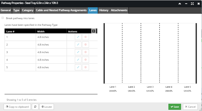
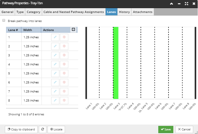
If Lanes are added to a Pathway Type, instances of that Type will automatically have the same Lanes, and those Lanes cannot be altered. The following screenshot shows an example of the Lanes tab in the Pathway Properties dialog for a Pathway instance that has Lanes specified in its Pathway Type. Notice that this Pathway instance already has Lanes defined and some of the controls are disabled, such as the checkbox at the top and the Action buttons in the grid. Also, notice the extra label "Lanes have been specified in the Pathway Type" is shown near the top, to indicate the reason behind those restrictions:
In contrast, if an instance of an ordinary Tray (without Lanes) is created, Lanes can be added directly to the instance. The screenshot image below and the accompanied text callouts cover this example. The former case is used when the physical tray product has built-in dividers, and the latter case is used when the dividers are added during installation or sometime later.
If Lanes are used, IRM tracks the utilization of each Lane separately in addition to the total utilization of the Tray, and you can choose which Lane a given Cable is routed through.
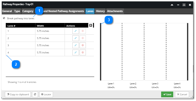
The screenshot image below shows an example of the Lane tab for a Pathway instance object with no Lanes previously specified in its Pathway Type, so that all controls are enabled:
 Break Pathway into Lanes checkboxThis checkbox determines whether a Pathway uses the Lanes feature, and enables or disables editing the Lanes list below.
-
If Lanes are specified in the Type, both this option the rest of the interface is disabled. -
Otherwise, if this option isn't checked, the rest of the interface is disabled. -
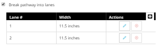
Otherwise, selecting (checking) this option enables editing of the Lanes grid. If there are no pre-existing Lanes, as shown in the example below, the grid will automatically populate with two Lanes, each of which occupies half the width of the Pathway, which is 23 inches in this example:
Note that these two default lanes cannot be deleted and therefore their x action button is disabled.
The Lanes grid will be explained in more detail in the next points.
|
|
 Lanes gridThis grid lists all Lanes specified for the Tray by their order number, also displaying their width and additional Action buttons for adding new, editing and removing existing Lanes.
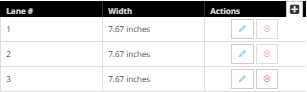
To add a new Lane, click on the + button. This automatically creates a new Lane placing it in the last row in the grid. The newly created Lane takes 1/3 of the total Tray width for itself, because the number of Lanes is now three and IRM borrows an equal portion from all existing Lanes.
Therefore, if the checkbox feature is enabled and the "+" button is clicked once, you will get three Lanes, each with 1/3 of the width. Clicking it again will result in four Lanes, each with 1/4 of the width, etc. If another Lane doesn't have enough width to lend, it lends what it can and its width is set to 0.
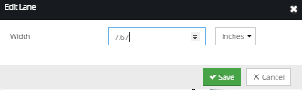
Each newly added Lane row has an x button for deleting it and pencil button for manually editing its width:
If you enter a width for a Lane manually, the UI adds or removes that width from other Lanes as necessary to keep the total width of the Tray correct.
-
If one Lane's width is increased, the width of the Lanes below is decreased. -
If one Lane's width is manually decreased, the width of the Lanes below gets increased.
In this way, the user can simply assign widths from the top down, where changing a Lane's width will not impact widths previously specified, unless that's the only way to keep the total width correct.
As mentioned earlier, the original two Lanes cannot be removed, but their length can be manually changed to another value.
Note that deleting a Lane will have the opposite effect of adding a new one in terms of other Lanes widths, that is, equal portions of the deleted Lane's width will be distributed to the remaining Lanes.
|
|
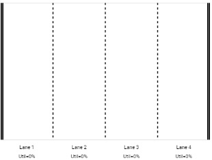
 Preview sectionThe Lanes grid Preview panel graphically shows the division of the Tray based upon its Lane configuration.
As mentioned in the introductory text, if a Tray is broken into Lanes and you start routing a Cable to it, you will be required to specify which Lane the cable will be routed over within the selected Tray.
Each Lane has its utilization tracked separately and this is also indicated in this Preview section by the Util label under the Lane name:
and also by a the colored bar in the Lane.
In addition to the utilization values displayed below each Lane, the Preview diagram also graphically shows per-Lane utilization by shading an appropriate fraction of each Lane in green color. The example screenshot image below shows a Tray with one of the Lanes (Lane 3) having Utilization around 37%, which is also visually indicated by the green fraction:
|
|