Defining Port Arrangements
The Port Arrangements tab in the Equipment Type Properties dialog enables specifying the visual arrangement of Port objects for the Equipment Type being defined.
This functionality is available through the Port Arrangement Properties dialog, which can be accessed in two ways:
-
by clicking on the Add Port Arrangement button, which is always enabled
-
by clicking on the Edit Port Arrangement button, which is enabled only when a Port Arrangement is selected
Determining a Primary Port
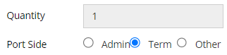
When defining a Port Arrangement it is important to determine if the Ports in the Port Arrangement being defined are to be considered as Admin (administrative port), Term (terminal port) or Other (other port).
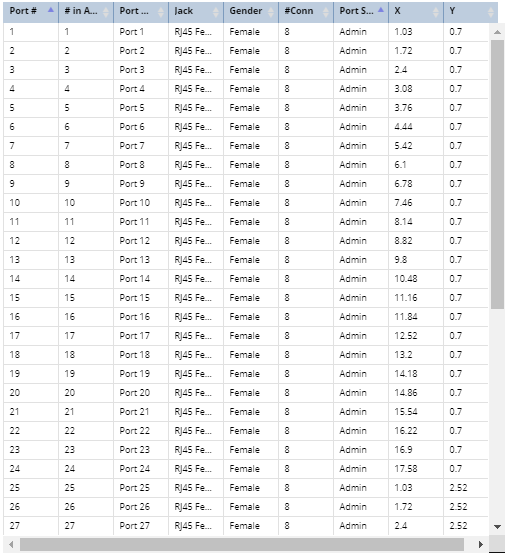
A Port Arrangement describes how how a set of similiar ports on a device are physically arranged and sets some important parameters for those ports. It allows the user to define, in a single operation, a set of ports that provide similiar functionality to each other and which are physically arranged in some regular/repeating fashion. This style of batch definition is particularly important for devices that support large numbers of ports that work the same way, such as 96-port patch panels.
A vital attribute for each Port Arrangement is the Port Side, which indicates the primary purpose of the port, as shown in the table below This parameter also plays a role in the Port Linking functionality, specifically in determining whether port linking is supported or not supported.
|
Port Side
|
Purpose of port
|
Examples
|
Supports Port LInking?
|
|
Admin
|
Allow the user to quickly change cable connections, for cabling that provides the primary business purpose of the equipment.
|
|
yes
|
|
Term
|
Provide a termination point for cables that are not frequently disconnected and reconnected, but which are involved in the primary business purpose of the equipment.
|
|
yes
|
|
Other
|
Any ports on the equipment that do not qualify as either Admin or Term. These are typically special control, upload, debug, power and other special purpose ports that do not directly provide the business functionality of the equipment.
|
|
no
|
Defining a Port Arrangement
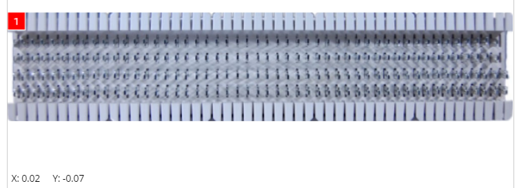
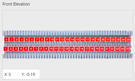
The following screenshot image shows an example of the Front Port Arrangement defined for a sample patch panel.
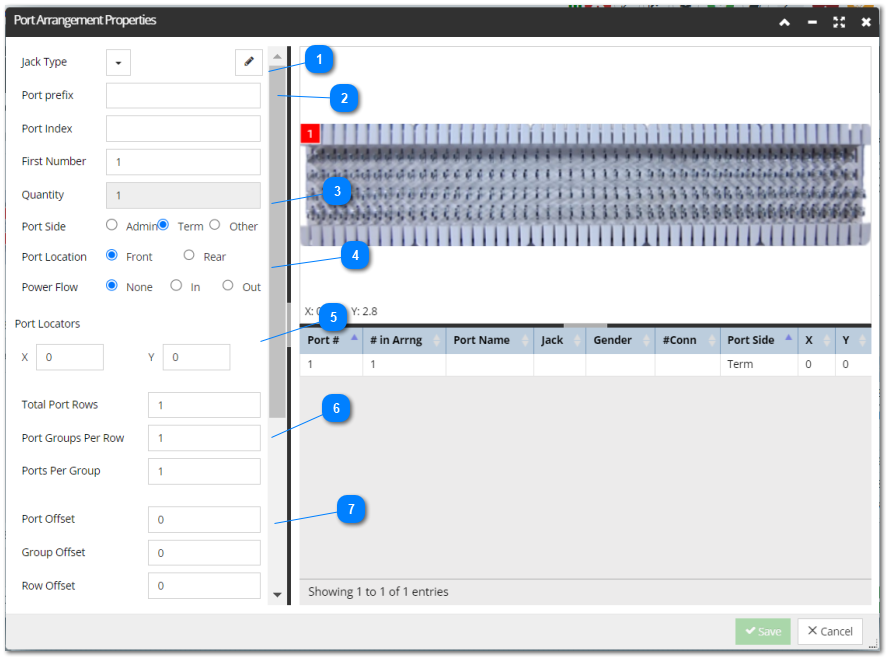
Note: All panels between the three sections of the dialog (left, top-right and bottom-right) are resizable. This is enabled by the dividers between each section, allowing the user to alter the layout to meet their needs. For example, in cases where the related Equipment Type has a relatively tall aspect ratio, that is, larger height then width, the drawing panel in the top-right of the Port Arrangement Properties can be easily adjusted so the needed details in the background image are more visible, making it easier for the user to get the Port positions aligned more precisely.
The following screenshot images and text explain the steps for specifying a new Port Arrangement for a newly created Equipment Type.
Partial write mode -- IMPORTANT
The Port Arrangement Properties dialog mostly operates in either read-only or read-write modes. However, there are situations where a partial write mode is necessary. Specifically, the Port Arrangement editor uses a partial write mode in the case where a Type is being referenced by equipment instance objects. Once instances of the Type exist, it is not safe to change attributes that the instances depend on. Just imagine what would happen if a Type was made with some ports, then instances were created and the ports connected with cables, and then the ports were removed from the Type. The ports in the instances would lose their definitions, which is critical information, and would therefore no longer work properly in IRM. As a general rule, the fields which can be changed in partial write mode are those that only affect visualization, while fields that affect the actual structure or non-visual nature of the object must remain read-only, to protect data integrity.
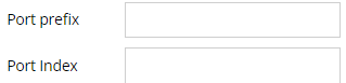
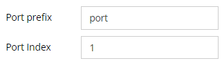
Specify the Jack TypeTo set up the Port Arrangement, start by selecting the Jack Type, also known as the Jack Definition. Within IRM, this definition provides detailed information about specific Port types, like the RJ-45 gigabit Ethernet port. Different Equipment Types commonly use these Jack Definitions.
By pressing the down-arrow button, a dropdown menu appears showcasing all available Jack Definitions. Additionally, there's a Quick Search box for swift and easy searching of the desired Jack Definition. In this instance, we've chosen the RJ45 Female Jack Type.
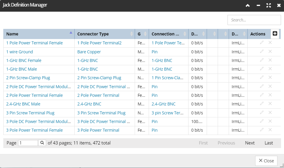
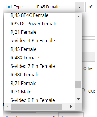 If the appropriate Jack Definition doesn't exist in the list, you can add a new one via the pencil button displayed on the right side of the Jack Type field.
which opens the Jack Definition Manager dialog. This dialog enables adding, editing and removing Jack Definitions and is explained in more detail under the parent topic about Defining Ports and Connections.
 |