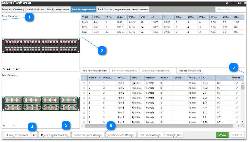
The Port Arrangements tab in the Equipment Type Properties dialog lists the existing Ports and enables their visual arrangement via Port Arrangements.
The purpose of this tab is to create both Port Definition (shown in the lower table in the screenshot below) and Port Arrangement objects (shown in the front and rear elevation images screenshot below). Each Port Definition gives the details of a single Port in that Equipment Type and is used only by that single Equipment Type object (Port Definitions are not shared across Equipment Types).
In addition, the set of buttons at the bottom of the dialog enables quick access to all other connection-related manager dialogs, such as those for Jack Definitions and Connector Types.
The following screenshot image and text explain the main functionality of the Port Arrangements tab:
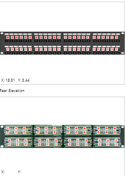
Front and Rear Elevation images
The left side of the dialog is reserved for displaying the Port Arrangement, separately for the Front and the Rear Elevation view of the selected Equipment Type. This section only enables simple zooming in/out and moving the image around. A similar visual editor is available when editing Port Arrangements and is covered in one of the sub-topics - Defining Port Arrangements.
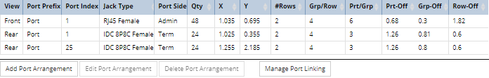
This top grid lists the existing Port Arrangements for the selected Equipment Type in a data grid and their properties. By default, nothing is selected in this or the bottom grid and only the Add Port Arrangement button is enabled.
IMPORTANT: The Add Port Arrangement mechanism is the only way that Ports can be defined in IRM.
Three key parameters determine how many Ports are defined and how they are arranged:
Ports per Group (Prt/Grp in the above table): a group is a set of Ports that are arranged contiguously horizontally, usually right next to each other. In the above front elevation example, there are 6 ports per group and for the rear elevation it shows 3 ports per group.
Groups per Row (Grp/Row in the above table): how many port groups there are in a horizontal row. In the above example, there are 4 groups per row on both the front and rear of the equipment.
Rows (#Rows in the above table): how many rows there are in the arrangement. In the above example, there are 2 rows on the front of the equipment and 4 rows in the rear elevation.
Note that both groups and rows are always "complete" -- not missing any Ports. If a group or a row is missing any Ports, more than one Port Arrangement must be used to model the Ports.
Clicking on any row in the top grid selects and highlights it in the top grid and also selects and highlights the corresponding Ports defined by the selected Port Arrangement in the bottom grid. This action also enables the other two buttons - the Edit Port Arrangement and Delete Port Arrangement buttons, which enable editing and removing the Port Arrangements listed in this grid.
Clicking on the Edit Port Arrangement button opens the Port Arrangement Properties sub-dialog, which is essentially the same dialog that opens on the Add Port Arrangement button click. See the following topic for a detailed overview of the Port Arrangement Properties dialog.
Clicking on the Manage Port Linking button opens the Port Linking dialog, which is explained in more detail in the following topic - Defining Port Linking.
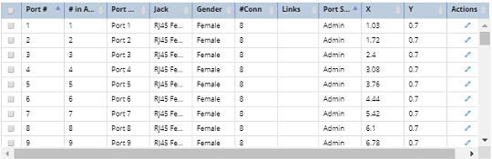
This grid lists all Port Definitions along with the following details:
Port # - is a generated sequenced number, starting from the number specified for the corresponding Port Arrangement. If a Port entry is added or removed this value is automatically re-sequenced.
# in Arrng - the order of the Port in the selected Port Arrangement
Port Name - the name given to each Port for identification.
Jack - the Jack Definition associated with the Port Definition that describes this Port
Gender - Male or Female
#Conn - the number of connection points defined for this Port
Links - list of linked Ports
Port Side - Admin or Term
X, Y - coordinates indicating the position of the Port within the device's front or rear face
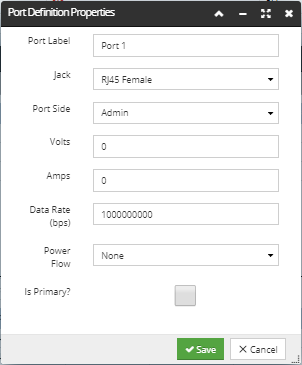
The Pencil action button opens the Port Definition Properties pop-out dialog, displayed below, which enables editing specific properties of the Port Definition, including electrical ratings (Volts & Amps) that can override the values from the Jack Definition or Connector Type. Also, Power Flow can be set for this Port, indicating whether it supplies power, receives power, or neither.
This button opens a dialog where the user can specify which Cable Plug Types can connect to a Port Jack Type. This compatibility list is used to restrict which Cables can be connected to specific Equipment Ports based upon the port's assigned Jack Type. Click on the following sub-topic for more details about this feature - Defining Jack Plug Compatibility.
Clicking on the this button opens the Connector Types Manager dialog, which enables adding, editing and removing Connector Types. Click on the following sub-topic for more details about this feature - Defining Connector Types.
Clicking on the this button opens the Jack Definition Manager dialog, which enables adding, editing and removing Jack Definitions. Click on the following sub-topic for more details about this feature - Defining Jack Definitions.
Before an Equipment Type object is used to create Equipment instance objects, the Equipment Type may be edited freely. However, after an Equipment Type object is used to create one or more Equipment instance objects, certain fields in the Equipment Type can no longer be changed. The restricted fields include Port Definitions, Slot Definitions and other fundamental characteristics, such as whether the Equipment is a rack or a peripheral. This restriction is occasionally inconvenient, but imagine the complications and potential confusion if you were to define an Equipment Type with several ports and use it to create many equipment instances, which then have cables plugged into those ports. Now you change the Equipment Type to remove the Port Definitions - what exactly should be done with all the instances of cables plugged into all the instances of the Equipment Type?
The corresponding situation in the real world is that a manufacturer can change a hardware design until it goes into production, but once the design is in production and especially after units have been shipped to a customer, it is impractical to physically alter those units by adding Ports, etc.
In such circumstances, the best option is to make a copy of the Equipment Type that must be updated, and make the necessary changes in that copy. Afterwards, IRM's equipment replacement function can be used to conveniently replaces instances of the original Type with those of the new Type, assuming that the new Type only has additional Ports, not removed Ports.
The contents of 4.4.1.2. Defining Ports and Connections