4.4.1.3. Defining Port Linking
IRM uses the concept of Port Linking to model the internal connections between ports in passive, or non-powered Equipment, such as patch panels and faceplates.
Port Linking allows for the following link options:
-
1:1 - The
admin port is linked to its
term port and is primarily used to represent port linking on patchpanels, faceplates and blocks.
-
1:x - This is allows a single port to be mapped to many ports and is primarily used to represent Multiplxing hardware such as DSLAMS, etc.
-
Uni Directional - This option will only allow path tracing allowed in the direction specified.
-
Bi Directional - This option allows path tracing to occur in both directions.
In order to support passive Equipment where the Administration (or Admin) and Termination (or Term) sides of a Port do not map 1:1, each side is defined as a separate Port Definition. Each side is linked with the other through port linking, which enables creating and removing connections / links between the Administration and Termination ports for an Equipment Type. If the ports are unlinked, it is no longer possible to trace a circuit path through the port and it therefore becomes the endpoint of a Path Trace.
Port Links
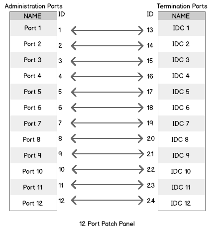
The following diagram shows the relationship between Admin and Term ports when the ports are all linked "straight across". This example shows a typical linking for a simple 12 port input/output device, such as a Patch Panel, where the Admin and Term ports have the same number of connection points. In this linking, each of the Administration ports map sequentially to each of the associated Termination ports. The Linkage determines the route a path trace takes through the device.
Unlinked Ports
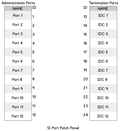
The following diagram shows the relationship between the Admin and Term ports when the ports are all unlinked. When no linkage exists between the Administration and Termination Port then any path trace will stop at the unlinked port.
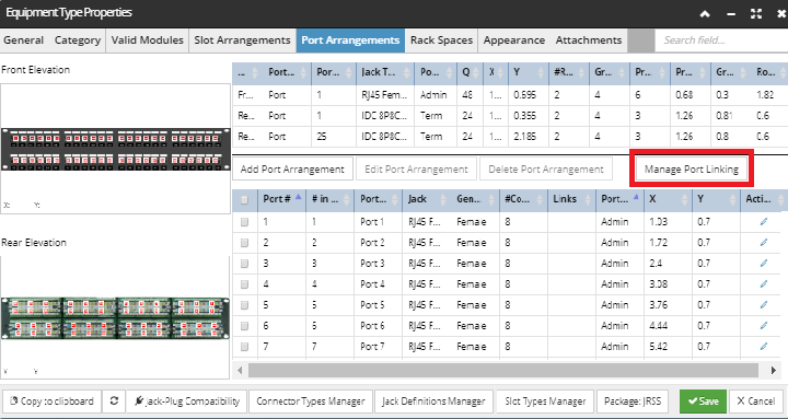
In IRM, the Port Linking feature is available through the Ports tab in the Equipment Type dialog. It is accessible from the Manage Port Linking button in the middle of the dialog and is only enabled when the Equipment Type has both Admin and Term ports (i.e. for passive equipment):
|
We strongly advise defining all Port arrangements and Ports first and then doing the Port Linking operation. In case you decide to change Port properties (like Admin/Term) after Port Linking operation, there's a chance Port Names will get re-arranged. So, in case you need to change such information after Port Linking, rather un-link any port linking previously made, do the change and redo the Port Linking operation.
|
The following screenshot images and text explain a use case of how Ports are mapped when the connection point count on each Admin Jack doesn't match the connection point count on the Term Jack.
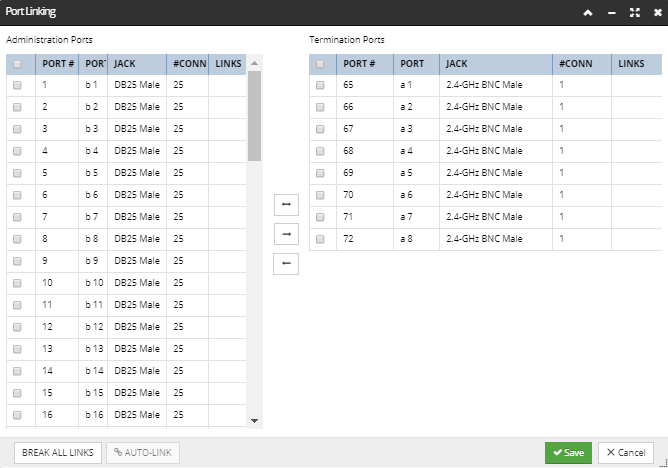
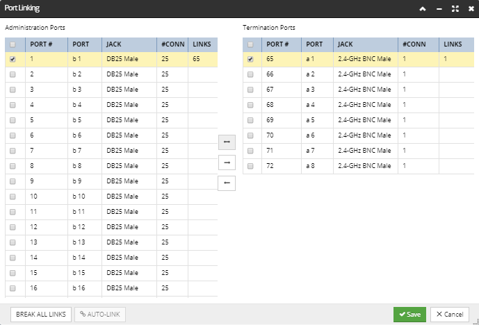
Case 1: Port Linking using Bi-Directional Option
With this link, if the path trace enters via port 1 then it will continue through port 65. Similarly, if the path trace enters through port 65 it will continue through port 1.
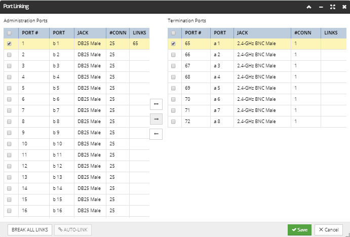
Case 2: Port Linking using Uni-Directional Option 1
With this link, if the path trace enters via port 1 then it continues through port 65. However, with this uni-directional Port Linking option, if the path trace enters through port 65 it will not continue through port 1.
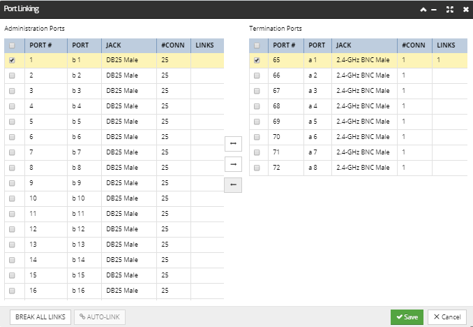
Case 3: Port Linking using Uni-Directional Option 2
With this link if the path trace enters via port 1 then it will not continue through port 65. If the path trace enters through port 65 it will continue through port 1.
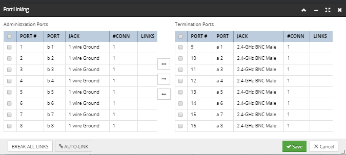
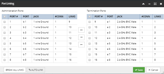
Case 4: Port Linking using Auto-Link
The Auto-Link button is enabled if and only if the total number of connection points is the same on the Admin and Term sides, regardless of whether the number of ports on each side is the same. For example, if there are 6 8-connector Admin ports and 2 24-connector term ports, auto-linking is enabled because both sides have 48 connections. Auto-linking only supports simple, "straight across" connections. In the following example, both the total number of connections is the same on the Admin and Term sides and the number of ports on each side is the same, which enables the Auto-Link button:
Clicking on it populates the Links columns appropriately, making a symmetric Port Link specification for the selected Port Arrangement(s).
In addition to supporting "straight across" and "one-to-many" links, the Port Linking dialog also supports the creation of "splitter" and "mux" (multiplexer) devices.
This is done by analyzing the ports on the Equipment Type and works as follows:
-
If the
connection counts of the Admin and Term ports differ, the dialog operates in a one-to-many mode, where a single port on the larger-connection-count side (which is usually the term side) can be linked to multiple ports on the smaller-connection-count side (which is usually the admin side). In this mode there is
no support for splitting or muxing, as the connection points are distributed from one port on the larger side across multiple ports on the smaller side.
-
If the
connection counts of the Admin and Term ports are the same, the dialog operates in the normal mode. In this mode ports can be linked one-to-one (as shown in previous examples), or one-to-many if more than one port is selected on one side, but only a single port is selected on the other side. This case of one-to-many is the case that
allows splitters to be modeled. Note that if multiple ports are selected on both sides, it's not a split / mux scenario, but rather an attempt to link multiple ports straight across.
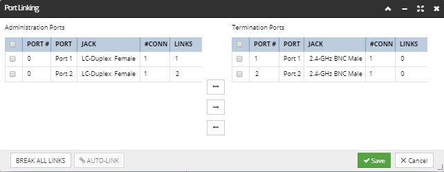
This way it is possible, for example, to create a bidirectional 1=>2 splitter / mux, where port 0 is split to ports 1 and 2 with all connection points mapped straight across. Port 0 has two links over the same connection points, which represents a split, while ports 1 and 2 link back to the same set of connection points on port 0, which represents a mux: