4.4.1.4. Defining Slot Arrangements
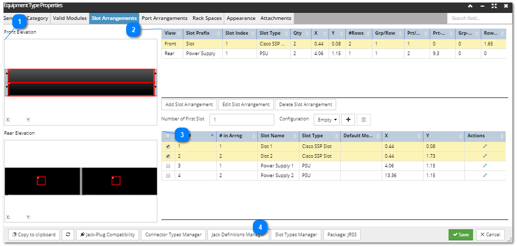
The Slots Arrangements tab in the Equipment Type Properties dialog lists the Slot Definitions and enables their visual arrangement for the selected Equipment Type. Each Slot definition (shown in the bottom table in the screenshot below) gives the details of a single Slot in that Equipment Type. Slot Definitions are not shared across Equipment Types; each Equipment Type has its own list. Slot Definitions are not added individually, but rather in groups defined by Slot Arrangements (shown in the upper table in the screenshot below).
The following screenshot displays the Slots Arrangements tab in Equipment Type Properties dialog:
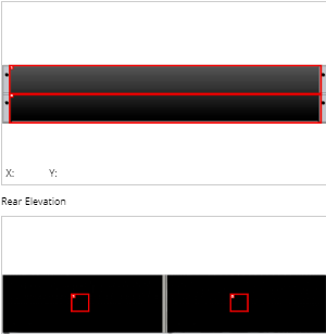
 Slot Arrangement panelThe left side of the dialog is reserved for displaying the visual arrangement of the Slot Definitions, separately for the Front and the Rear view of the selected Equipment Type.
|
|
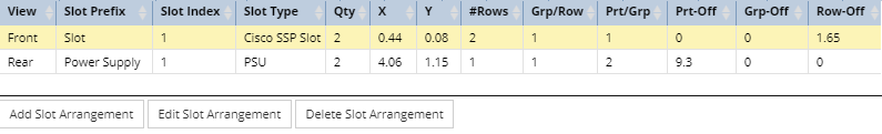
 Top gridThis top grid lists the Slot Arrangements for the selected Equipment Type.
By default, nothing is selected in this or the bottom grid and only the Add Slot Arrangement button is enabled.
Selecting a Slot Arrangement in the grid causes the corresponding Slot Definitions in the bottom grid (displayed and explained in more detail in the next point).
This action also enables the other two buttons displayed under this grid - the Edit Slot Arrangement and Delete Slot Arrangement , which enable managing the existing Slot Arrangements listed in this grid.
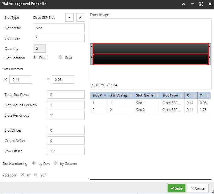
Clicking on the Edit Slot Arrangement button opens the Slot Arrangement Properties sub-dialog, which is the same dialog that opens on the Add Slot Arrangement button click. The screenshot image and text below explain it in more detail:
The dialog is divided into several sections, as listed below:
-
the left section enables specifying different Slot Arrangement parameters: -
Slot Type, which can be selected from the list of existing Slot Types. The Slot Type determines the data rate of the Slot and also the size of its visual representation in the Elevation dialog and in the Slot Arrangement Properties dialog above -- that is why there are no size parameters as part of the Slot Arrangement itself.
-
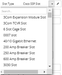
the pencil icon on the Slot Type row opens the Slot Type Manager dialog, which can be used to add, edit and delete Slot Types as explained in more detail in the last point of this topic -
Slot Prefix (text) and Slot Index (numeric) values, which, in combination, specify the Slot Name
-
Quantity, which is set automatically based on the Total Slot Rows, Slot Groups Per Row, and Slots Per Group parameters (described below)
-
Slot Location, which can be Front or Rear
-
values of the Slot Locators, which are specified as X and Y coordinates for positioning the Slots relative to the front or rear face of the equipment -
number of Slots Per Group, Slot Groups Per Row, and Total Slot Rows, all specified as numeric values. These values are defined the same as the similarly-named Port Arrangement parameters: -
Slots per Group: a group is a set of Slots that are arranged contiguously horizontally, usually right next to each other.
-
Slot Groups per Row: how many groups there are in a horizontal row.
-
Total Slot Rows: how many rows there are in the arrangement.
-
Slot / Group / Row Offset value, also specified as numeric values. These offsets are in inches and indicate, respectively:
-
the distance between each Slot (measured from the left edge of one Slot to the left edge of the next Slot) -
the extra space between each Slot Group -
the offset from one row to the next (measured from the top edge of one row to the top edge of the next row) -
Slot Numbering, whether it is by Row (Slot 2 is directly to the right/left of Slot 1) or by Column (Slot 2 is directly below or above Slot 1)
-
Rotation of the Slot, whether it is 0 or 90, which translate into vertical or horizontal orientation
-
the top-right Front Image section displays the visual arrangement of the Slot arrangement being edited/created, with the specified X and Y Slot Locator values being shown
-
the bottom-right section contains a data grid displaying the individual Slot Definition properties, which are automatically derived from the parameters specified in the left section
Note: All panels between the three sections of the dialog (left, top-right and bottom-right) are resizable. This is enabled by the dividers between each section, allowing the user to alter the layout to meet their needs. For example, in cases where the related Equipment Type has a relatively tall aspect ratio, that is, larger height then width, the drawing panel in the top-right of the Slot Arrangement Properties can be easily adjusted so the needed details in the background image are more visible, making it easier for the user to get the Slot positions aligned more precisely.
|
|
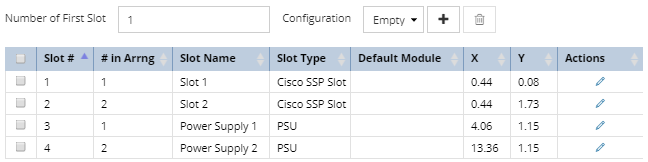
 Bottom gridThis grid displays all Slot Definitions specified by the Slot Arrangements. When a Slot Arrangement is selected, the corresponding Slot Definitions are also selected. The grid shows the following properties:
-
Slot # - is a generated sequenced number. If a Slot entry is added or removed this value is automatically re-sequenced.
-
# in Arrng - the order of the Slot in the selected Slot Arrangement
-
Slot Name - the name given to each Slot, derived from Slot Prefix and Slot Index
-
Slot Type - the Slot Type is used to only allow supporting cards/modules to be inserted based upon it having a compatible Slot Type.
-
Default Module - A Default Module is the Equipment Type of a compatible card, system board, or other module that can plug into this Slot. When a new instance of the current Equipment Type is created, an instance of the default module is also created. This way, an Equipment Type Chassis and its pre-installed modules can be configured to be a single Equipment Type. Therefore, an Equipment with several sub components can be created all at one time, rather than creating several different objects and plugging them together individually.
-
X, Y - coordinates of the Slot Locators indicating the position of the Slot within the device
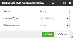
The Pencil Action button opens the Edit Slot Definition - Configuration <Name> sub-dialog,
which enables editing the following properties for the selected Slot Definition under the selected Slot Configuration:
-
Name of the Slot Definition
-
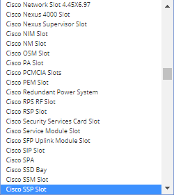
Interface Type, specified by selecting one of the values from the drop-down list of existing Interface Types
-
and finally, the Default Module, also selected from the drop-down list of existing compatible Equipment Types.
In the section immediately above the grid, the user can specify different Equipment Type Configurations. A configuration of an Equipment Type specifies the set of Default Modules for the Slots. There is always a starting Configuration named "Empty", that is created by the application and which cannot be deleted. Therefore, Equipment Type will always have at least one Configuration and the appropriate Slot Definition will always have at least one Default Module. The user can add additional Configurations. When a different Configuration is selected, the dialog updates the Default Module column, which parallels the Configuration Name.
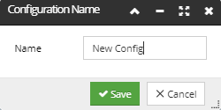
Clicking on the + button opens a small Configuration Name sub-dialog, which enables specifying only the Name of a new Slot Configuration,
while saving it causes it configuration to be added and selected/applied to the currently selected Slot Arrangement.
The trashcan (delete) button next to the + button causes the currently selected Configuration to be deleted. The button is disabled if the Empty Configuration is selected.
|
|
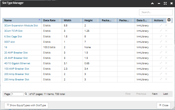
 Slot Types Manager buttonClicking on this button at the bottom of the Equipment Type Properties dialog opens the Slot Types Manager dialog, which lists all existing Slot Types, along with their basic properties, in a paginated data grid and enables adding, editing and removing them by Action buttons.
To make it more convenient to see the list of Equipment Types that use a specific Slot Type, there is dedicated button at the bottom of the dialog that opens the Slot Type Manager dialog.
Note: The user can also use the Filter Manager to find the same list, but it does take some time to create the right filter, so we recommend using this button as a convenience.
Click on the button sets the Equipment Type tab in the main Object grid as active and effectively applies a "has any Slot Definitions" filter to the Equipment Type tab. Next, the Confirmation dialog opens with a message saying "The list of Equipment Types that use a Slot Type is shown in the Object Grid". Conveniently, this dialog also shows the "Don't show this message again" checkbox, so the dialog doesn't appear again until the site reloads.
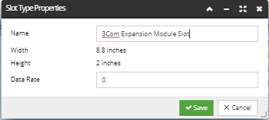
Clicking on the pencil Action button opens the basic Slot Type Properties sub-dialog, which enables editing the Name and the Data Rate values of the selected Slot Type:
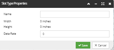
Clicking on the + Action button opens the same Slot Type Properties sub-dialog, with the exception that all fields are set to default values or empty:
As usual, clicking on the x Action button removes the appropriate Slot Type, with the Warning dialog previously asking for confirmation.
|
|
Partial write mode
The Port Arrangement Properties dialog mostly operates in either read-only or read-write modes. However, there are situations where a partial write mode is necessary. Specifically, the Port Arrangement editor uses a partial write mode in the case where a Type that is currently put into read-only mode due to the fact it's being referenced by other objects.
As a general rule, the fields which can be written in partial write mode are those that only affect visualization, while fields that affect the actual structure or non-visual nature of the object are still read only, to protect data integrity.
Specifying Port Names for the Equipment placed in a Slot configuration
The name of a module’s Port is determined by a combination of information from the Arrangement for the the Port and the Arrangement for the Slot that it’s plugged into. To get the name of a Port of something, for example a module, plugged into a Slot, a number is appended to the name Prefix field from the module’s Port Locator. The number is set to the first "Child Alphabetic Index" from the Slot’s Arrangement, if that is not the empty string, otherwise it's set to the "first Child Number". This number is incremented over all the Ports in the front Arrangement (if any), then starting again from first Child Number (or first Child Alphabetic Index), the number is incremented over the rear Ports.
Example:
Let's assume the following properties are set:
-
the front Arrangement for the module has the "name Prefix" set to ”Front ”
-
the rear Arrangement for the module has the "name Prefix" set to ”Rear ”
-
the Slot’s Arrangement’s first "Child Alphabetic Index" set to “A“
-
child "Number Increment Per Slot" is set to "2"
As a result, the following sequence of Slot names is set, assuming two-Port modules are used:
Slot 1: Front A
Rear A
Slot 2: Front C
Rear C
For a single Port module in Slot 1 and a two-Port module in Slot 2, the following sequence of Slot names will be used:
Slot 1: Front A
Rear A
Slot 2: Front C
Front D
Rear C
Rear D
To conclude, for most scenarios, the parameters are set as follows:
-
default first Child Alphabetic Index == ““
-
-
child Number Increment Per Slot == 0
For the faceplates of interest ( & to supply the exact list), we can use the following values instead of the above: For select faceplates
-
first Child Alphabetic Index == A
-
-
child Number Increment Per Slot == 2