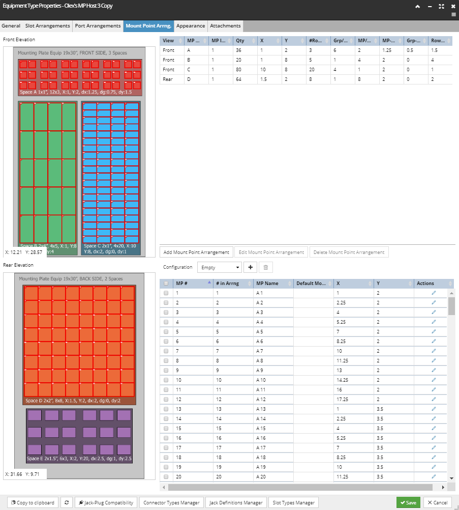
The Mount Point Arrangements tab in the Equipment Type Properties dialog enables specifying the visual arrangement of Mount Points for Equipment Types that support mounting other Equipment on its front or rear. A Mount Point Arrangement defines a rectangular region containing a matrix of discrete Mount Points. The screenshot below shows three Mount Point Arrangements on the front of an Equipment Type, using different shapes, sizes, and group offsets. Note that this Equipment Type is an artificial test case used to demonstrate Mount Point Arrangement features and is not a realiistic Equipment Type example.
In Arrangements where the Mount Points are immediately adjacent, it is possible to mount Equipment objects that occupy more than one Mount Point; this happens often when circuit breakers are mounted on panel boards, which is one of the primary use cases for the Mount Point Arrangement feature.
Basic dialog features:
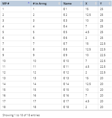
Functionality is similar to the Equipment Type Slot Arrangement and Port Arrangement tabs, with the Mount Point visualization on the left and Mount Point data on the right side of the dialog.
By default, nothing is selected in either grid and only the Add Mount Point Arrangement button is enabled.
Selecting a Mount Point Arrangement in the upper grid also selects the corresponding Mount Points in the bottom grid. This also enables the other two buttons under the upper grid for editing and removing the existing Mount Point Arrangements.
Clicking on the Edit Mount Point Arrangement button opens the Mount Point Arrangement Properties sub-dialog, which is the same dialog that opens on the AddMount Point Arrangement button click.
Note: In the following text, the abbreviation MP will be occasionally used instead Mount Point
The following is a step-by-step use case scenario of adding a new Mount Point Arrangement to the existing Equipment Type via the Mount Point Arrangement Properties dialog:
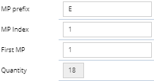
Define Mount Point Name Prefix, Index and the First Mount Point index
The first step is to specify the following parameters:
the MP prefix, which is usually a text string
the MP Index, which is usually a numeric value and together with the MP prefix forms the full Mount Point name
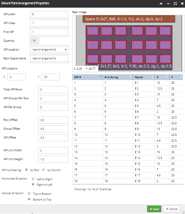
the First MP Index, which defines the starting number for the Mount Point Index, which can be seen in the visualization on top-right of the dialog (see ).
For this example, if we specified the MP prefix as E, MP Index as 1 and First MP as 5, that will result in Mount Points named "E 1", "E 2", etc. until MP <n>, where <n> is the quantity of Mount Points being defined. The First MP will affect only the number of the starting MP in the arrangement in the visualization.
Quantity is a read-only field and is populated by the application once the rest of the parameters are specified.
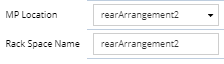
The Mount Point Location field specifies the Rack Space of this Mount Point Arrangement and can be one of the following pre-defined Rack Spaces :
Front 1, 2, 3
Rear 1, 2, 3.
Each Mount Point Arrangement is "generic" in that there is no difference in behavior for either of the three front or rear spaces, other than the shape, size, and number of Mount Points as defined by the Arrangement.
An Equipment Type can have only a single Rack Space location specified for a single Mount Point Arrangement. If one Rack Space location is selected for a MP Arrangement, it is no longer available for selecting in this drop-down menu for any other Mount Point Arrangement. This way, you can never have more then six total MP Arrangements for an Equipment Type.
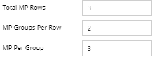
Specify the number of Port Rows, the number of Port Groups Per Row and the number of Ports per Group
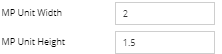
These parameters determine how many Mount Points are defined and how they are arranged:
Total MP Rows: how many rows there are in the arrangement.
MP Groups per Row: how many groups there are in a horizontal row.
MP per Group: a group is a set of Mount Points that are arranged contiguously horizontally, usually right next to each other.
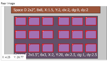
The total number of Mount Points generated by the arrangement (shown as a read-only Quantity under item 1 above) is the product of these three parameters, that is, Total MP Rows x MP Groups per Row x MP per Group. This means, that, for example, for the values specified in the screenshot image, the number of total Mount Points would be 3 x 2 x 3 = 18.
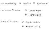
Mount Point numbering can go either first across each row, then to the next row, or first up or down a column, then on to the next column. The ordering within a row can be left-to-right (most common) or right-to-left. The latter case often occurs on the back side of passive equipment like patch panels so that the port numbering on the back physically lines up with the port numbering on the front. Ordering in the vertical direction can be top-to-bottom (most common) or bottom-to-top.
More specifically, this section enables specifying the Mount Point Numbering via the following properties;
whether it is by Row (MP 2 is directly to the right/left of MP 1) or by Column (MP 2 is directly below or above MP 1),
whether the Horizontal Direction is from Left to Right (MP 2 is directly to the right of MP 1) or Right to Left (MP 2 is directly to the left of MP 1),
and whether the Vertical Direction is from Top to Bottom (MP 1 is directly above the MP 7) or Bottom to Top (MP 1 is directly under the MP 7).
Changing any of these values from the default ones will affect only the number of the Mount Points, not their position.
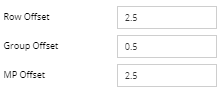
The Rear Image section displays a detailed visual arrangement of the Mount Point arrangement being specified. The image can be zoomed in/out and moved around by using the mouse, in the same way as in Port Arrangement and Slot Arrangement tabs.