Dependency View diagram
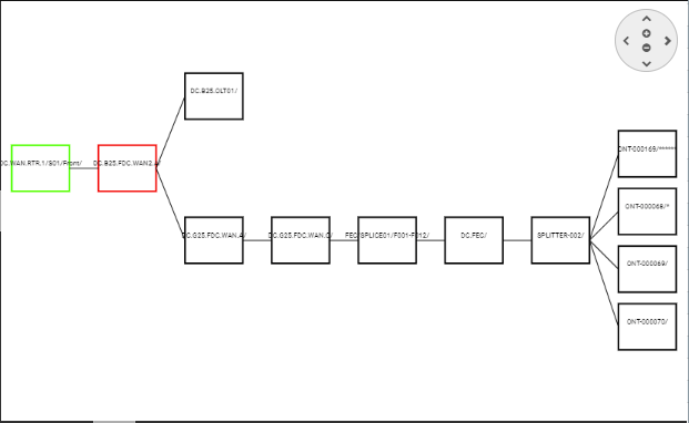
The main diagram displays two types of objects
-
Nodes, which represent Equipment objects, are drawn as rectangles
-
Links, which represent Cables or Slots, are drawn as lines between Nodes.
Each element is selectable, causing more information to be displayed in the appropriate data grid. All objects are color-coded to represent different types of objects as it follows:
Nodes (Equipment objects) can be displayed in:
-
red – the currently selected equipment / node
-
green – active equipment / node (e.g., routers, switches, computers)
-
black – passive equipment / node (e.g., patch panels, faceplates)
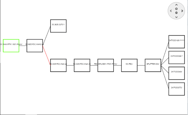
Connection links can be displayed in:
-
Cable link – solid, black
-
selected Cable link – solid, red
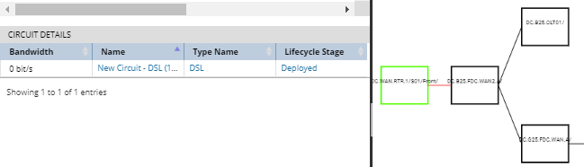
A solid line from one node to the next node represents one or more Port – Plug – Cable – Plug – Port connections between the nodes. That is, even if there are several Cables connecting the two Equipment objects, only a single line is is drawn. If the selected connection / line represents any Cables that are assigned to Circuit(s), the appropriate Circuit Properties submenu will list all such Circuits and basic information about them:
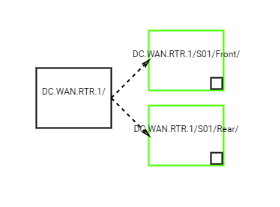
A dashed line from one node to the next node indicates that the target Node is a card or module that is plugged into a Slot in the source Equipment. The "target Node" is the one at the end of the dashed line that has the arrowhead and the "source Node" is the one at the other end. This way, both parent and child Equipment are displayed as nodes, with the containment relation displayed as dashed black line:
The Dependency View allows navigating and changing the view size through the schematic view by clicking on the pan / zoom control, similar to the one in the Design World.  The same actions can be achieved by clicking and dragging the mouse for navigation and scrolling the mouse wheel to zoom in and out.
The same actions can be achieved by clicking and dragging the mouse for navigation and scrolling the mouse wheel to zoom in and out.The Dependency View generates the model based upon every connected port on each Node shown in the Dependency View, allowing the user to see the full connectivity dependencies. It is also possible to "drill down" on any node in the Dependency view, which opens a new instance of the Dependency View on the selected object.
The Dependency schematic diagram also enables displaying the path trace dependencies for selected object. This is very useful to determine which down-flow or up-flow objects in the path based upon path trace connectivity are dependent on the selected equipment object. Please see the next topic for more details.