Importing and connecting Rack/Cabinet Equipment
This and the next topics contain a common use case scenario that covers some specific features of Spreadsheet / DDR import. This subtopic covers the scenario of importing Cable objects from a CSV file into an existing Rack and connecting its Rack Equipment with that Cable. It's not necessary for the imported Cable objects to connect to any existing Equipment, but this example was intentionally selected to show how to use all of the features of DDR Cable Import.
Important note: This use case has many of the same steps as the one covered in the previous sub-topic, so only the parts which are different are covered in more detail (mostly in Step 2 - Column Mapping).
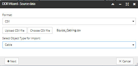
 Select source dataThe first step covers the process of uploading the spreadsheet for the appropriate type of object and specifying appropriate import options. The Spreadsheet / DDR Import feature is represented as a multi-step wizard dialog, accessible from the application's Main Screen, by click on the DDR Import button located above the Object Grid, which opens a new wizard-style (multi-step) dialog displaying the first step of the DDR Import Wizard - Source data:
-
First set the data source via the Format drop down menu (CSV or URL). In this example CSV format is selected, as we will upload a spreadsheet from a local directory.
-
Then click the Upload CSV file button, which opens the Upload file dialog, displayed in the screenshot below. Clicking on the Select file button opens the standard browser file upload dialog. After selecting the file, its name is displayed in the File to upload grid, along with its size, status and an additional action button for removal. Clicking on the Upload button animates the Progress bar, indicating the progress of the file upload, and closes the dialog and brings focus back to the DDR Wizard dialog.
-
Set the target IRM object type associated with the data source - this is enabled by selecting the object type associated with the data source by clicking on the Select Object Type for import drop-down menu. Since this is an example of importing Cable objects from a CSV file, the Cable Object Type is selected from the drop-down.
|
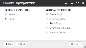
 Specify the Import Parameters
|
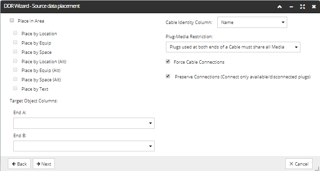
 Source Data PlacementIn this step, first we specify what type of marker to search for in the source file (i.e. Place By Text) and the column in the uploaded CSV that contains that value.
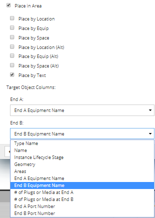
In addition to the common placement options shown here, it is also possible to specify the End A and End B fields for the cable endpoints. This enables importing Cables between any type of Endpoint identifier (Location, Space, Equipment or Text), which provides a consistent a common approach for defining placement options when using DDR import for all objects. Finally, not all cables require connecting during DDR Import, therefore, it is not a requirement to map the End a Port or End B ports before being able to import the cable.
None of these fields are mandatory – however, if any of "End A/B Port Number", or "# of Plugs or Media at End A/B" fields are mapped, then "End A/B Equipment Name" field must also be mapped. In other words, you cannot specify some Plugs to be connected without saying which Equipment it's connect to.
If, for example, the "End A/B Equipment Name" field is mapped, but the "End A/B Port Number" field isn't, then the "# of Plugs or Media at End A/B" defaults to 1 and "End A/B Port Number" defaults to either 1, or the first free Port number. This depends whether the preserve Connections field is set to true, in which case it will be set to the first free Port number, or false, in which case it's set to the default value (1).
-
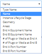
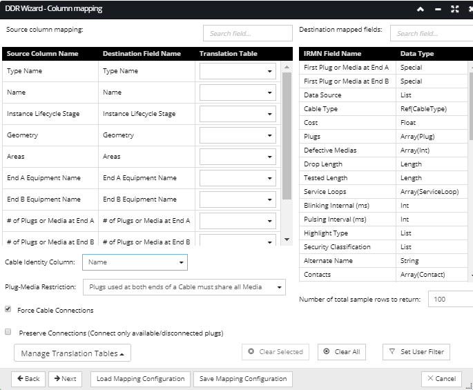
In order to allow multiple rows in the spreadsheet to correspond to a single Cable, we allow the user to specify which CSV column can be used to determine which rows correspond to the same Cable object. This Cable Identity Column can be chosen via a drop-down that lists appropriate columns in the CSV. For example, if the CSV has a column named "CableNum", which is mapped to "Name", then the "CableNum" would appear in the drop-down. In our example, the Cable Identity Column " Name" is selected. This allows the set of connections for a single Cable object to be spread across multiple rows in the CSV, but note that those rows MUST be contiguous.
-
Plug-Media Restriction gives the user options on how to handle cases where the Plugs at each end of the Cable are connected to different Media. The following options are available:
-
Plugs used at both ends of a Cable must share all Media - a CSV row is considered "valid" only if all the plugs at End A collectively use the exact same set of Media as all the Plugs at End B, otherwise it's an error. Note that IRM does not try to check the correspondence between any specific Plugs, it just checks that all the Media used at End A are the same as all the Media used at End B. This drop-down value is selected by default, is appropriate for most cases, and is left selected for this example.
-
Plugs used at both ends of a Cable must share some Media - a CSV row is considered "valid" if each End A Plug shares at least one Media with some End B Plug; otherwise the row is invalid and generates an error
-
Plugs used at both ends can use completely separate Media - no checking is done for common Media between the Plugs at each end of the Cable. This allows the user to handle special cases without generating errors.
-
In cases where the special cable connection fields (End A/B Port Number, First Plug or Media at End A/B, # of Plugs or Media at End A/B) are not mapped or they are mapped but some row(s) don't have legal values, the user may want to force connections anyway by using IRM defaults for those fields. The Preserve Connections option is meant for this purpose -- if it is unchecked, then IRM only makes cable connections if the relevant fields are mapped and the rows have good values, but if it is checked, IRM will attempt to make connections even if some of the cable connection fields aren't mapped or don't have good values for some rows.
|
 Step 2: Column MappingThe DDR Import Wizard - Column mapping dialog is the second screen displayed in the DDR Wizard Interface. This step is for the most part the same for all object types, but there are some specific options enabled only for Cables.
The following features are available in this step of the DDR Wizard, when importing Cables:
-
Mapping columns in the Source CSV file to IRM fields for the appropriate Super Category. The mappings from CSV columns to IRM fields are handled by appropriately selecting the row entries in the Source and Destination grid and either defining a new mapping by double clicking on the Destination field, or clearing any existing mapping by clicking on the Clear Selected button on the bottom of the dialog. When this wizard step is first entered, any CSV columns whose names match IRM field names (modulo case) are automatically mapped. In our example, all necessary fields are auto-mapped in this way, so there is no action needed in this part of the dialog. For some types of objects, there are mandatory Destination fields that need to have a corresponding Source field specified for mapping . It's not possible to proceed with the next step of the DDR Import Wizard if those fields are not mapped, which is indicated (see the previous sub-topic for an example of DDR Import - Importing and connecting Rack/Cabinet Equipment).
-
Using Translation Tables to consistently replace specific data values in the CSV file with alternate data. Note that Translation Tables can be chosen on a per-field basis, allowing a considerable amount of control in adapting the CSV data to the needs of the import operation. Also, Translation Tables can be managed (viewed, added and removed) via the Translate Table Manager that is accessible via the Manage Translation Tables button. In this example we do not specify any translation tables.
-
Because the CSV may have many columns, a Quick Search box is provided to help the user locate a specific column (filter the column list on the left side of the dialog). For this example, we don't specify search fields to filter the Source Column list.
-
Because the Target IRM Super Category may have many fields, a Quick Search box is provided to help the user locate a specific field (filter the field list on the right side of the dialog). For this example, we also don't specify search fields to filter Destination Column list.
The screenshot below displays the final specification of a column mapping, while the text below explains all steps made until this point in more details:
Click on the Next button on the bottom of the dialog to proceed with the next step of the DDR Import wizard.
Important Note: An additional restriction is that all rows for a given Cable must be contiguous in the Source CSV file.
|
 Step 3: Data PreviewThis screen is the last step of the DDR Wizard interface. It displays some result data of the configured CSV Import listed in a data grid, along with additional properties and action buttons. The resulting data grid contains an entry for each CSV row (excluding the header row, of course), up to the maximum indicated by the Total sample rows to return (a field in step 2 above). Additionally, the result data grid also contains entries corresponding to any rows beyond the specified number of sample rows to return that generate an error a or warning (result of No match, Missing Type, or Invalid data), up to an additional Total sample rows to return items.
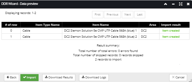
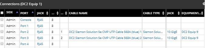
In our example all rows are successfully imported and the only action left to finish the DDR Import operation is to click on the Import button, which closes the DDR Wizard dialog and brings focus back to the main application screen and the Design World. Once the Elevation dialog of one of the previously imported Racks is opened, it can be seen that the DC2 Equip1 and DC2 Equip9 instances were successfully connected with the DC2 Siemon 5e UTP Cable, as displayed in the Ports and Connections tab:
|
|