Importing Faceplate Equipment into Areas via DDR
This section will review all steps and available options available when importing Equipment object into an Area via the DDR Import Wizard.
Note that the focus will be on specific options and features available for this particular use case, while the common details already described in detail in the introductory topic will be covered briefly.
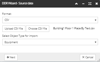
When importing Equipment to be placed into an Area the user will need to define the following fields in an CSV import file:
|
Field Name
|
Description
|
|
Area
|
The name of the Area within which the Equipment will be placed eg. Building 1 Floor 1
|
|
Type Name
|
The name of the Equipment Type as defined in the Equipment Type database e.g. Nordx 2 Port Cat6 Faceplate
|
|
Name
|
The equipment name to help identify the Equipment being imported. e.g. WA0001/A
|
|
Instance Lifecycle Stage
|
The lifecycle stage to be assigned to the imported Equipment, e.g. 'Deployed'
|
|
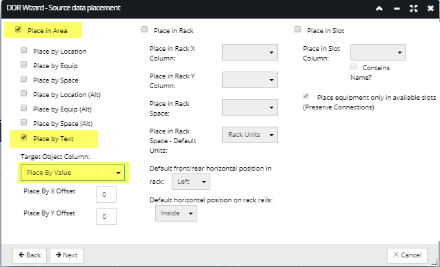
Place By Value
|
The Place By Value is used to identify how and where the equipment being imported will be placed within an Area and can contain or reference any of the following values:
|
The following is a worked example showing how to import faceplates to Text String located in the Imported CAD File:
Specify Import ParametersSpecify the CSV Identity Mode and the CSV Identity Mode by clicking on one of the radio buttons:
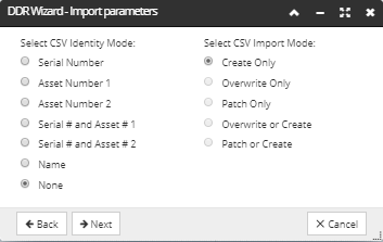 Setting the CSV Identity value specifies how the data from the CSV records is matched against existing IRM objects. Note that, in addition to None and Name, for Equipment object types there are additional CSV Identity Modes available for selection:
Setting the CSV Import value specifies whether new objects are created from the CSV data or existing IRM objects are overwritten by matching CSV objects. Please refer to the introductory topic for more details about what each Import Mode means.
For this example, we will leave the None and Create Only default values for import parameters.
IMPORTANT: Successful matching is critical in order to do updates of existing objects and to avoid creating duplicated objects. The difference between Overwrite and Patch is that Overwrite updates the entire target object, whereas Patch only updates the fields explicitly supplied in the CSV file. In most cases, the Patch modes are more appropriate.
|
Column MappingThis tab is used to map the additional data columns for Area, Type Name, Name and Instance Lifecycle Stage.
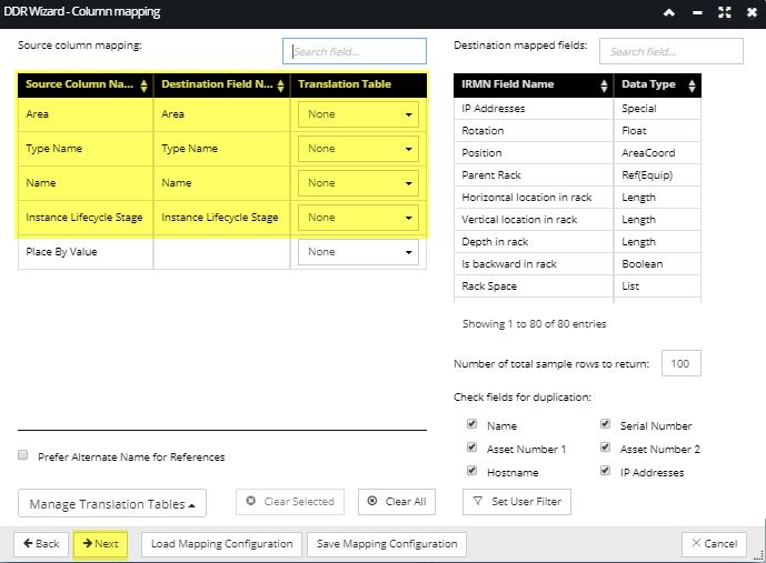 Note: When the column name in the CSV matches the column name in the Wizard, the fields will be auto-mapped.
WARNING: Duplication checking can be computationally expensive when large DDR files are imported into a Site with large numbers of Equipment objects (hundreds of thousands or more).
|
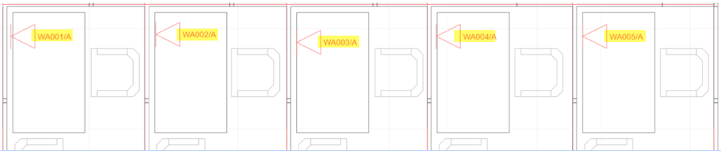
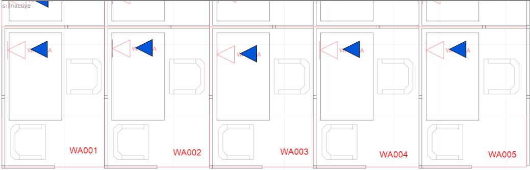
DDR Import ResultsNotice the Equipment is placed exactly at the text String specified in the CSV Import File:
 Note: The user can specify an X or Y offset value in the Source Data Placement tab which can be used to specify an offset from the text string.
If we re-imported the same CSV file but this time specify an X Offset of -12 the results would be appear as follows:
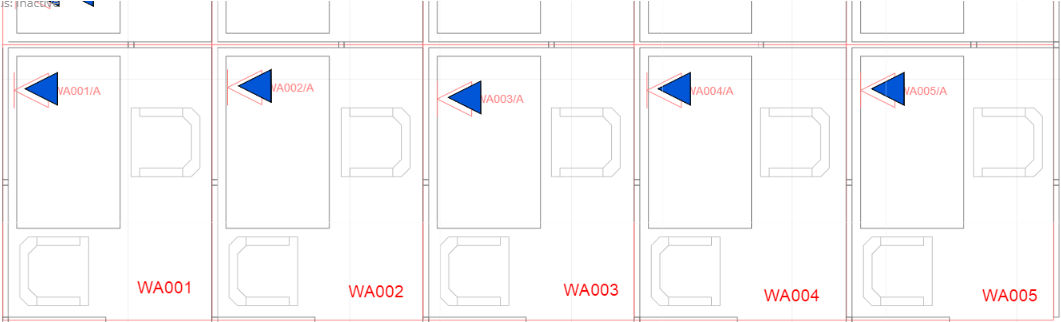 Note: by specifying an offset of -12 the imported faceplates are moved 12inches to the left.
|
IMPORTANT: In case when the DDR import includes multiple types of placement in a single operation, the critical Equipment characteristics, such as IsRackMountable, IsRailMountable, IsSubcomponent) must be set correctly in order for the code to understand what kind of placement it should be trying to do. If otherwise, the application will return the "PlaceBy object not found" error message.