4.5.5.1. Test Fiber SenSys equipment
The following use case demonstrates how to create and test Fiber SenSys equipment and Fiber SenSys add-on functionality inside the IRM application, using the Fiber SenSys SDK simulator. Connecting to actual Fiber SenSys hardware is similar, just skip the simulator-related steps.
Note: For a successful operation the Fiber SenSys integration must be enabled in the IRM license.
Upon a successful installation, you should be able to locate the "FSI.Simulators.Client.exe" file under the
Fiber SenSys SDK installation Client folder. This file runs the simulator application, and as a result, opens the
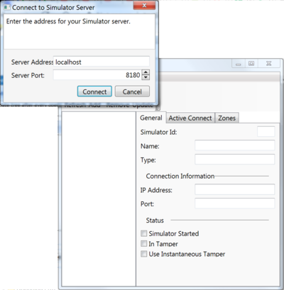
Connect to Simulator Server dialog. Continue with the below, and also see the Fiber SenSys documentation for more information about the simulator.
Enter the IP address and connect to the Simulator Server
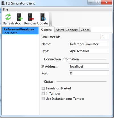
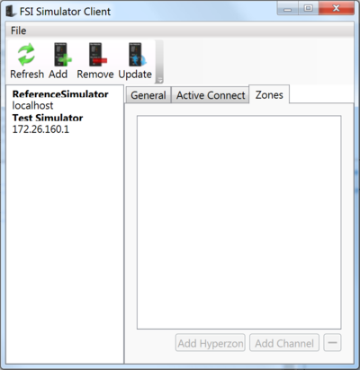
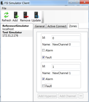
Inside the "Connect to Simulator Server" dialog, enter an appropriate IP address into the Server Address field and confirm by clicking on the Connect button. As a result, the FSI Simulator Client dialog opens:
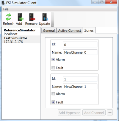
Next, you will configure a new Simulator -- start by clicking on the Add button on top of this dialog.
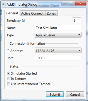
Configure a new Simulator
The Add Simulator dialog opens, where you can configure the General tab as displayed in the screenshot image below (use an IP address appropriate for your network):
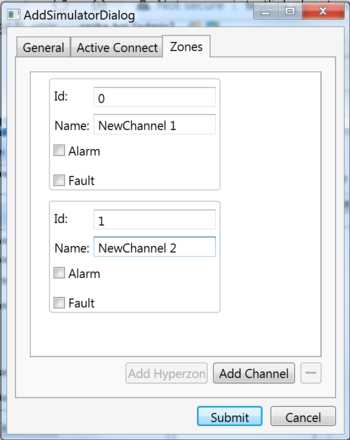
Next, configure data in the Zones tab as follows:
Note: Simulator Id must be unique, and IP Address may differ from what is shown above - in this case, select the option offered in drop-down list.
This creates a new simulator with two channels, which is added and can be viewed on the left side of the FSI Simulator Client dialog.
Open a new instance of IRM with Fiber SenSys component included
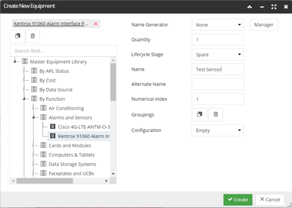
Use an instance of IRM with the Fiber SenSys component included in the License. Inside IRM, open the Equipment tab in the Object Grid, start creating a new Equipment instance by click on the + button on the top left of the gird. This opens the Create New Equipment dialog, which should be configured as follows:
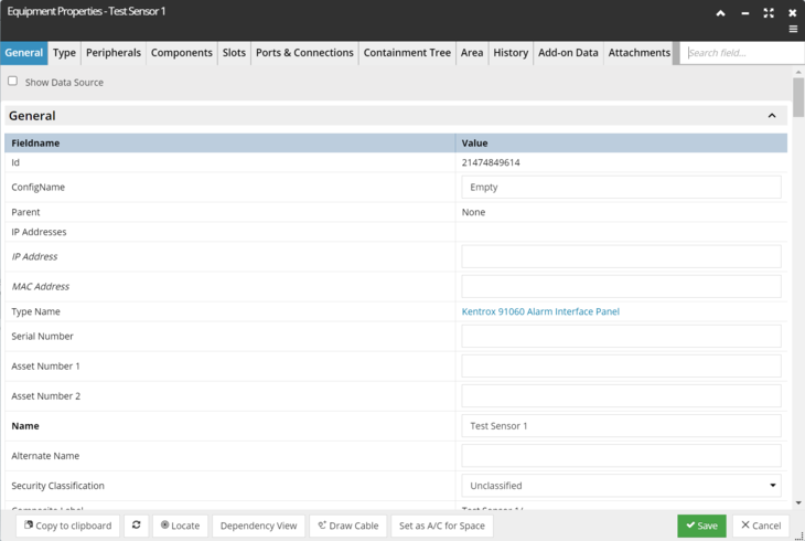
Click the Create button - this closes the dialog and opens the Equipment Properties dialog for the newly created Equipment instance:
Configure the IP address for the selected Equipment instance
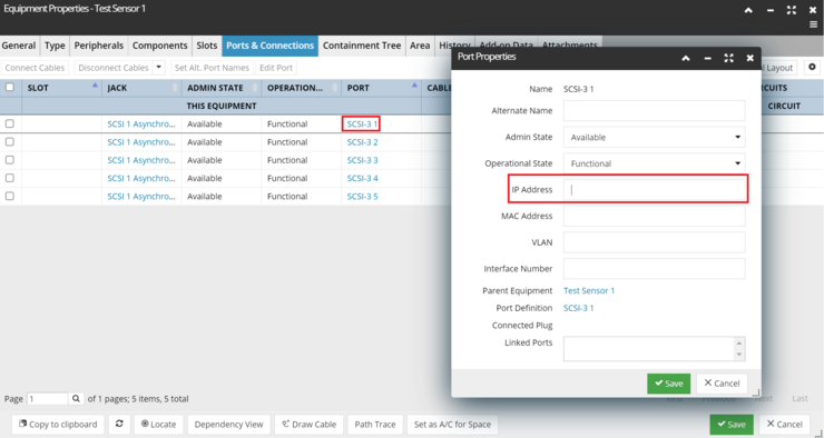
Inside the Ports and Connections tab, select a Port under the same-named column. This opens the Port Properties sub-dialog, where you can add the same IP Address as in step 3 under the appropriate field. Confirm the changes by click on the Save button, which closes this sub-dialog and brings focus back to the previous one.
Note: This IP address can be used and will work only on ONE machine and port. If it was already added to some port on some machine, it will not work on another machine until removed from the first one. Ask your colleagues if you think this IP was already used by someone.
Here, click the Copy to Clipboard button and also confirm the changes by clicking on the Save button, which closes the dialog.
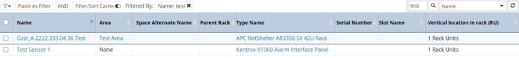
The newly configured Equipment instance appears in the Object grid, with the IP address configured for one of its Ports.
Add the newly configured Equipment instance to the FiberSensSys Proxy Source
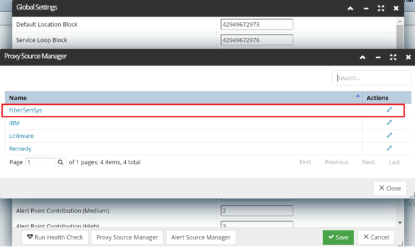
Open the Proxy Source Manager from the Global Settings dialog (gear icon in the top-right corner of the main screen) and locate the FiberSenSys Proxy Source in the list:
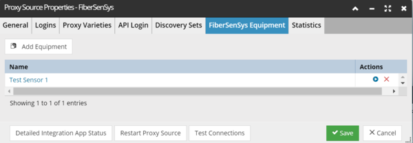
Clicking on the FiberSenSys Proxy Source opens the FiberSenSys Proxy Source Properties dialog.
Inside the FiberSenSys Equipment tab, click the Add Equipment button on the top - this automatically adds the previously configured Equipment to this FiberSenSys Equipment list (the Equipment is already copied to clipboard in the previous step).
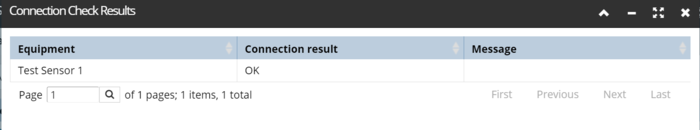
Test Connection
This is done by clicking on the Play Action button, which opens a pop-up sub-dialog displaying the Connection Check Results, which is OK in our example:
Close this dialog and click the Save button in the Proxy Source Properties dialog, which closes it and brings back the Proxy Source Manager dialog.
Update the Simulator Zones properties
Go back to the FSI Simulator Client dialog and change properties under the Zones tab as shown in the screenshot below, in order to cause an Alarm and a Fault:
Save the changes by clicking on the Update button on the top.
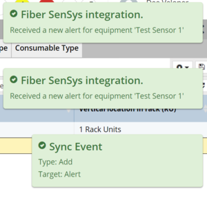
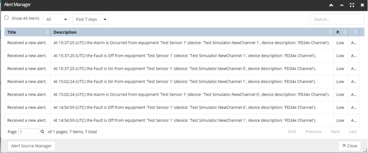
Within the IRM application, check that the following notifications appear (subject to the user settings for such notifications):
-
The notifications arrived:
-
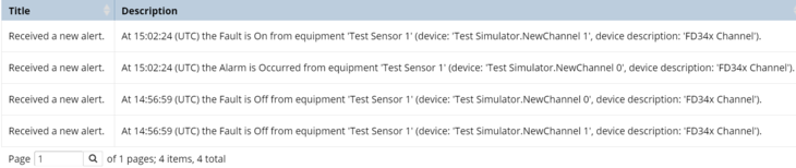
Also, inside the
Alert Manager dialog, the Alert entries about Channels status update should be correctly displayed, along with the associated Alert info, such as the time and channel status.
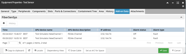
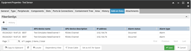
Check the associated Equipment Add-on Data
In the IRM application, locate the Equipment instance configured through steps 4-5 and open its Equipment Properties dialog. Inside the Add-on Data tab, expand the FiberSenSys accordion menu and check that:
Channel status update entries are displayed
the Alert data, such as time and channel status is correctly displayed and does not differ from the alert data in the Alerts Manager dialog from the previous step.
Change Zones properties again and update the Equipment
In the FSI Simulator Client dialog, change the Zones properties again - at this step, you should enter different values than under step 8 and update the equipment by clicking on the Update button at the top of the dialog.
In IRM, check that:
the notifications arrive
In the Alert Manager dialog there are alerts about Channel status updates
Alert info (time, channels status) is correctly displayed
Open the configured equipment
Next, inside the Add-on Data tab, expand the FiberSenSys accordion menu and click the Refresh button at the bottom of the dialog. Check that the data in the Add-in data tab was refreshed, and the new data corresponds to that entered in the previous step.