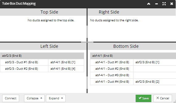
This button is located in the bottom of the Tube Box diagram and allows the user to view and manage how the innerducts ae mapped within the Tube Box using the Tube Box Duct Mapping dialog:
This dialog is divided into four panels - one for each side of the Tube Box (top, bottom, left and right).
The first column in each section, represents the tubes and innerducts terminated within that section of the Tube Box. The second column in each section, represents how the specificed innerduct is connected to another innerduct located within the same Tube Box.
In the above example:
The ABF Tube named abf2/3 is terminated on the left side of the Tube Box and contains 2 innerducts:
abf2/3Innerduct #1 connects to the ABF tube named abf4/1 Duct 1 [1] which is located at the Bottom of the Tube Box.
abf2/3Innerduct #2 connects to the ABF tube named abf4/1 Duct 1 [4] which is located at the Bottom of the Tube Box.
The ABF Tube named abf4/1 is terminated on the bottom of the Tube Box and contains 4 innerducts:
abf4/1Innerduct #1 connects to the ABF tube named abf2/3 Duct 1 [1] which is located on the Left of the Tube Box.
abf4/1Innerduct #2 is not connected to another innerduct.
abf4/1Innerduct #3 is not connected to another innerduct.
abf4/1Innerduct #4 connects to the ABF tube named abf2/3 Duct 1 [2] which is located on the Left of the Tube Box.
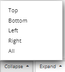
Each list is two-level data grid, with the upper level being the outer ducts and the lower/leaf level being the inner ducts. The lists can be collapsed to show only the outer ducts or any given outer duct nodes can be expanded to show their inner ducts. This is done simply by clicking on the Collapse or Expand drop-down buttons, which, in addition, allow the user to select either one of the individual lists to expand/collapse, or to do it for all the lists:
Duct Mapping rules
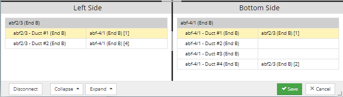
The mapping itself is be done by selecting a left-side inner duct, a right-side inner duct, and then clicking on the “Connect” button. In case either of the selected Ducts is already connected, the button shows “Disconnect” instead, and clicking on it then disconnects whichever of the selected ducts is connected (which can be one, the other, or both).
The mapping can also be done by selecting on one side, then double-clicking on the other side. That breaks any existing connections involving the selected ducts and connects them. Each list has a column that indicates the name of the outer duct and number of the inner duct that this inner duct is connected to. In the example above, this could be something like "abf-4/1 (End B) [1]" to indicate inner duct 1 of outer duct abf-4/1.
IMPORTANT: If an innerduct has a cable routed through it, it is greyed out in the mapping dialog and cannot be connected or disconnected until the cable is removed from the route.