4.3.1. Area Management
An Area represents some region of space in the real world, such as a floor in a building or the outside plant of a campus. It is the topmost mechanism for organizing the data within a Site.
Note: an Area in the new web-based IRM roughly corresponds to a Site Workspace in the Windows desktop client IRM.
In IRM, Areas provide the primary interface used by all users to interface with the configuration data stored in the area and IRM library.
An Area models a specific region of space in the enterprise and is used to contain collections of data, including:
-
Floor Plans
-
Room Layouts
-
Datacenters
-
Geo-spatial Maps
-
Site Plans
-
Entrance Facilities & Maintenance holes
-
Telecommunication Rooms
-
WAN Diagrams
Every Area can be displayed on a Canvas to display graphical information such as its associated drawing representation. The Canvases and associated menus and controls are sometimes referred to as the Design World. An Area is also assigned a coordinate system, which may or may not be the same coordinate system used by other Areas.
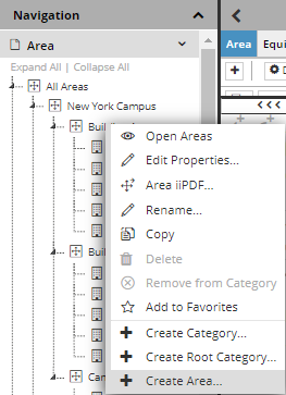
There are two ways to create a new Area in IRM:
-
by selecting the Create Area... option from the Area Category context menu in the C&T menu:
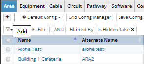
-
by click on + button in the Area tab in the Object Grid
These actions open a new Area Properties dialog with default values. The following use case explains the sets of property fields that define an Area. After their values are set, creation of the new Area is confirmed by clicking on Save button, which closes the Area Properties dialog and brings focus back to the main application screen.
The following text and images will explain the main parts of the Area Properties dialog:
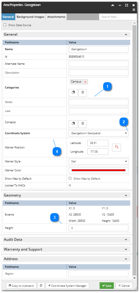
Categories field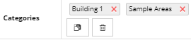 When an Area is defined via the Categories and Types Tree, the appropriate Category is automatically assigned and displayed as a label. Additional Categories can be assigned by clicking on the Paste button, which
assigns the object currently located in the Clipboard (assuming it's a Category). For more details about the Clipboard feature, see the following topic - Quick View.
|
Coordinate System drop-down menuThis drop-down menu enables setting a Coordinate System for the newly created Area:
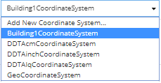 If the desired Coordinate System is not in the list, an additional one can be created selecting the Add New Coordinate System... option from the list. This opens the Coordinate System Editor dialog with the default field values set.
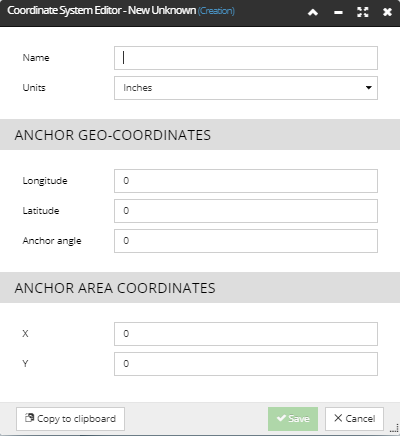 Once the appropriate values are entered and saved, the newly created Coordinate System is listed in the drop-down menu.
Whether to reuse an existing Coordinate System or create a new one depends on the relationship between this Area and other Areas and the floor or site plan data that is imported. The general rule is that if two Areas
have comparable coordinates, that is if any particular numeric coordinate values have the exact same spatial meaning in both Areas, the Areas should share the same Coordinate System, otherwise they shouldn't.
General Guidance for Co-ordinate systems:
For more details about this feature, see the following topic - Coordinate Systems.
|
WARNING: In case the Save button isn't enabled, in general there is a good chance it's because some mandatory field hasn't been filled out, or somehow got deleted or omitted. Make sure you specify all mandatory fields (field name in bold font), especially upon a new object creation.