Cable Schematic View is a special-purpose dialog used to display the media connectivity for a given Cable object in a schematic form allowing the user to understand how a cables media is routed and/or spliced and terminated.
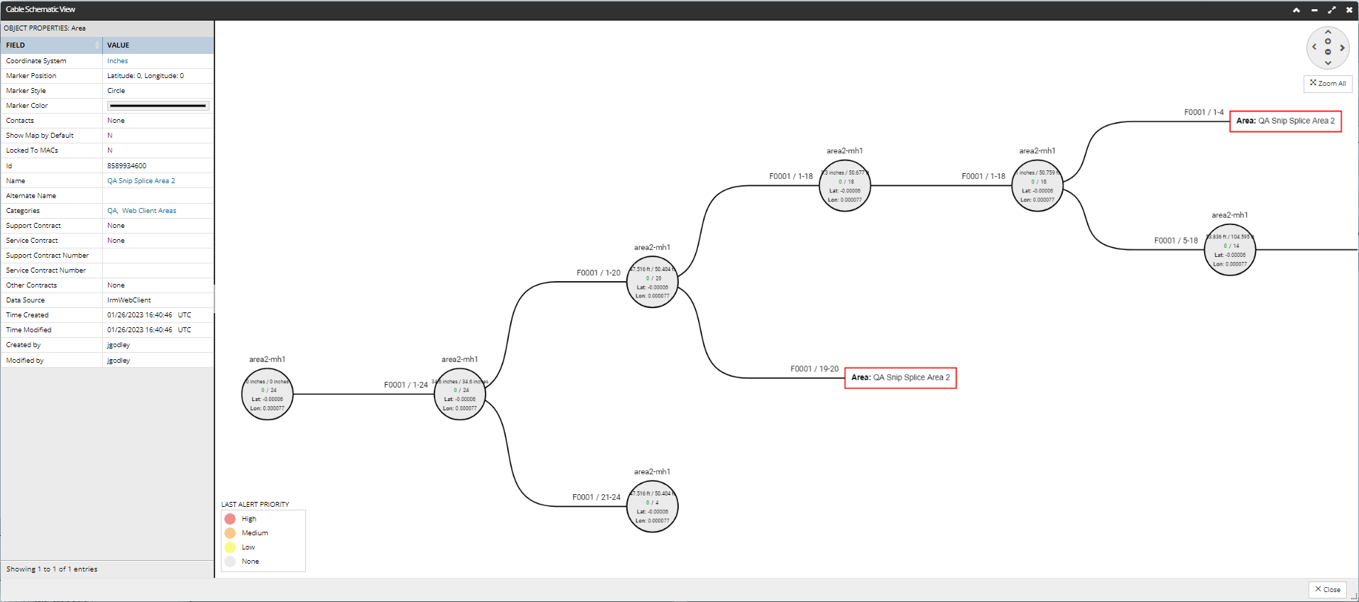
The following example shows the Cable Schematic for a 24 Strand Fiber Cable named F0001. The diagram shows the cable starts and a mainteanchole named area2-mh1 and then shows how it is routed and spliced and where each media group terminates:
Additionally, the dialog also displays related Equipment and Area objects, in both the visualization panel and the data grid. The visualization shows the source Cable's route up to the next splice point or termination point, with its length and name displayed as text above it.
The purpose of this dialog is to demonstrate the physical connectivity of various media in a particular Cable, starting from one end. The labels and the overall diagram can look quite different when starting from the other end of the Cable, or from some other Cable that this Cable is spliced to. Each media is traced through splices – even if those splices are to other Cables -- but not across any other kind of connection. If a media from the original Cable end is spliced to some other media, regardless of which Cable that media is from), the trace continues over the spliced Cable/media and the line that represents that Cable is given the label of the original Cable and the original Cable’s media numbers.
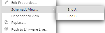
The diagram starts at a user-specified end of a Cable and all labels are from the point of view of the starting Cable in the Design World.