Tutorial - Splicing Cables Example 2
The following is a step-by-step tutorial that demonstrates how to splice a multi-Area Cable in the Design World with another independent multi-Area Cable. In the case of Snipping, a prerequisite is to have the desired Cable already drawn in the designated Areas.
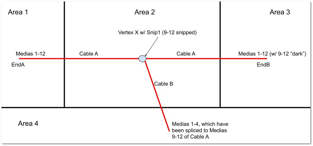
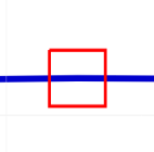
Below is a diagram of the Cable splicing layout to be achieved:
The black lines represent area boundaries, while the red lines signify cables.
-
Cable A runs from Area 1, passes through Area 2, and extends to Area 3. In Area 2, medias 9-12 from cable end A are cut(snipped) at a certain vertex, denoted by the grey circle icon. Medias 9-12 remain dark (unused) between Area 2 and Area 3. However, these medias could potentially be reused at the Snipped location idetified as Snip1B by splicing them to another cable or connecting them to an equipment port.
-
Cable B is created independently from Cable A but is designed to be compatible with the medias of Cable A. All the medias of Cable B are spliced to medias 9-12 of Cable A within Area 2, allowing it to route to a different location — Area 4.
Step 0 (Prerequisite) - Cable Creation and Placement
As mentioned in the introduction, cable splicing can only be executed via a cable context menu in the Design World. This requirement necessitates the cable to be placed in the designated Design World Area before any snipping or splicing operations can take place. For the purpose of this tutorial, Cable A has already been created, positioned, and routed through all the designated areas as depicted in the layout design above.
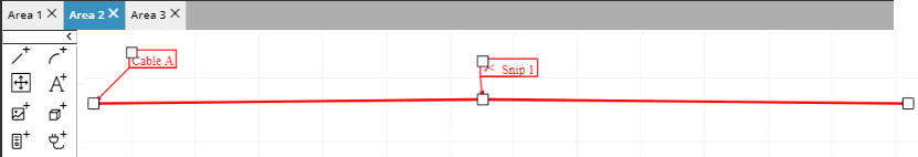
Furthermore, it is indicated that medias 9-12 of Cable A are snipped in Area 2 (as shwn below). Since the snipping procedure has been previously detailed in another section of this tutorial, we will move forward by showcasing the result of the cable snip through the following screen shots:
The following is a multi-Area Cable route that starts in Area 1 is routed through Area 2 and is continued into Area3.
In Area 2 the cable media 9-12 was snipped creating 2 new cable ends at the snip point.
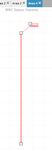
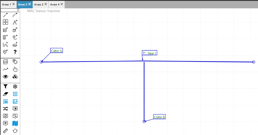
A new cable is routed from Area 4 to the Snipped cable point in Area 2.
Step 1 - Select Splice.. option for Cable A
To splice the media at the snip point in Area 2 to the new cable routed from area 4, the user opens Area2 and right clicks at the snip point and selects Splice from the context emnu.
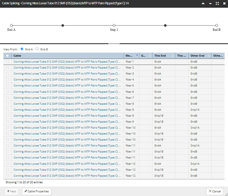
This opens the Cable Splicing dialog.
Step 2 - Select the Cable Media to Splice
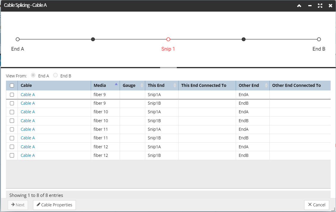
Select a node in the simplified schematic, which causes the data grid below it to enter “focus mode”, based on the selected node, which is Snip 1 in our example:
Note: Observe that in focus mode, the data grid displays only the Media ends that are located at the selected node, which is Snip 1 in this instance. The selected node determines the contents displayed in the This End column set, whereas the Other End column set contains whatever is at the opposite ends of those Media segments.
In our example, as expected we have both the A end and B end of medias 9-12 to work with.
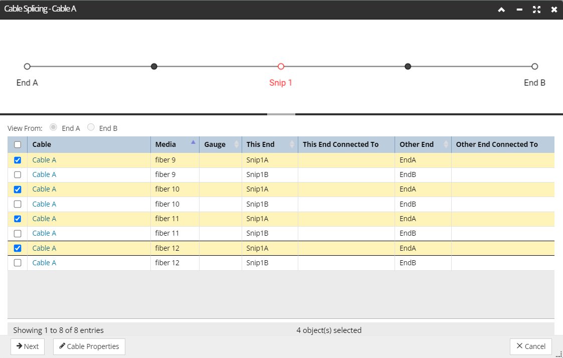
Step 3 - Make Splice - Choose Source Media
For this example, Medias 9-12 of Snip 1A Cable End are selected. Next, click the Next button.
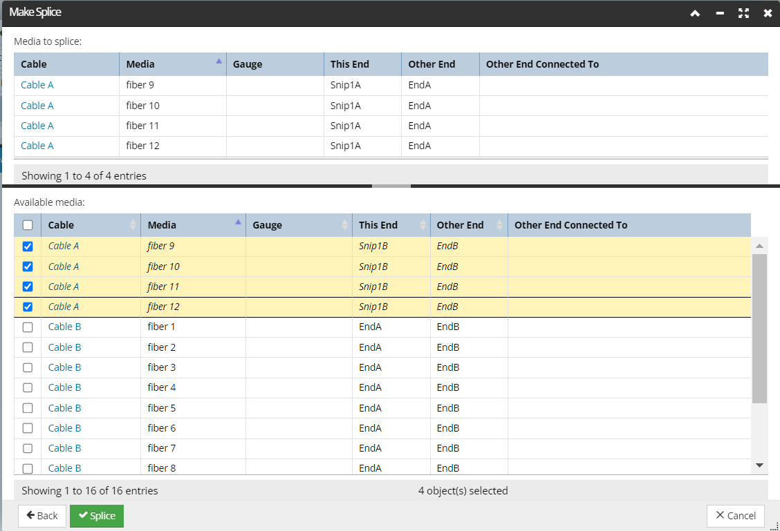
This closes the current Cable Splicing dialog and opens another dialog - Make Splice as shown below:
The user can now chosse the cable media to Splice into by selecting teh starintg meia. i.e. by selection Cable B fiber 1 will automatically splice sequentially as follows:
|
Cable A
|
Cable B
|
|
fiber 9
|
fiber1
|
|
fiber 10
|
fiber 2
|
|
fiber 11
|
fiber 3
|
|
fiber 12
|
fiber 4
|
Make Splice dialog features
The Make Splice dialog is also divided into two horizontal sections, each featuring a data grid:
-
The top grid lists the media selected for splicing, very similar to the data grid from the previous Splice dialog.
-
The bottom data grid lists all nearby Media ends available for splicing. Since there may be multiple cables with ends near the splice point, this data grid shows an additional
Cable name column at the beginning. As a general rule, the rows in this sub-dialog include all Media ends near splice point, from any cable, where:
-
The Media Material of the Media is the same.
-
The gauge of the media is the same (applicable to fiber Medias only).
-
The Media ends are not currently connected to anything.
Important: Other Media ends from the same cable are included in the list, so that it is possible to splice together the exact same Medias that were previously snipped. Notice the Media ends from the same Cable are displayed in italic font.
The Splice button at the bottom of the dialog is initially disabled - to enable it, a row entry from the bottom Available Media data grid needs to be selected.
To proceed, the user selects the exact same number of Media ends in the sub-dialog as in the main splice dialog, in which case the Splice button is activated. Pressing this button (when activated) will close the dialog, redirecting focus back to the Design World Area and the involved cable, now represented with a rectangular icon denoting the added splice.
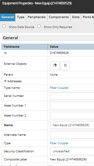
When the mouse is hovered over this icon, the user can notice this is actually a newly created Equipment object -- a Coupler -- and as such, can be viewed via the standard Equipment Properties dialog: