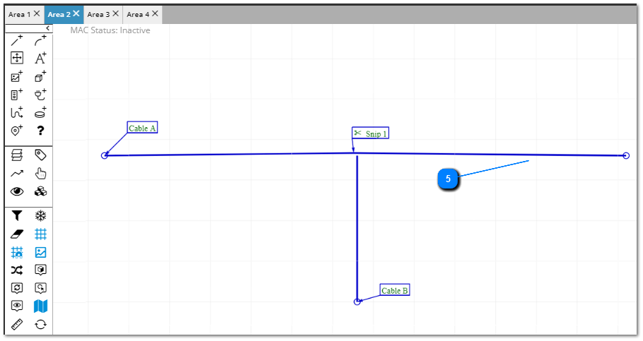
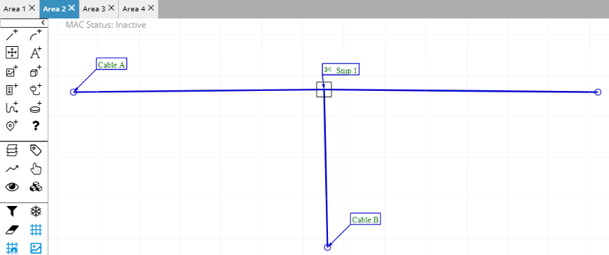
The following screenshot shows the existing Cable arrangement in Area 2, where both Cable B and the snipped Cable A are located and from there continue on to other Areas(as indicated by the small circle icons at the ends of the Cables):
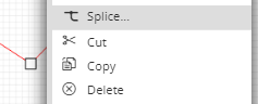
To invoke the "Splice.." dialog
Select the cable to be spliced i.e. cable A and then select Splice from the selected cables context menu.
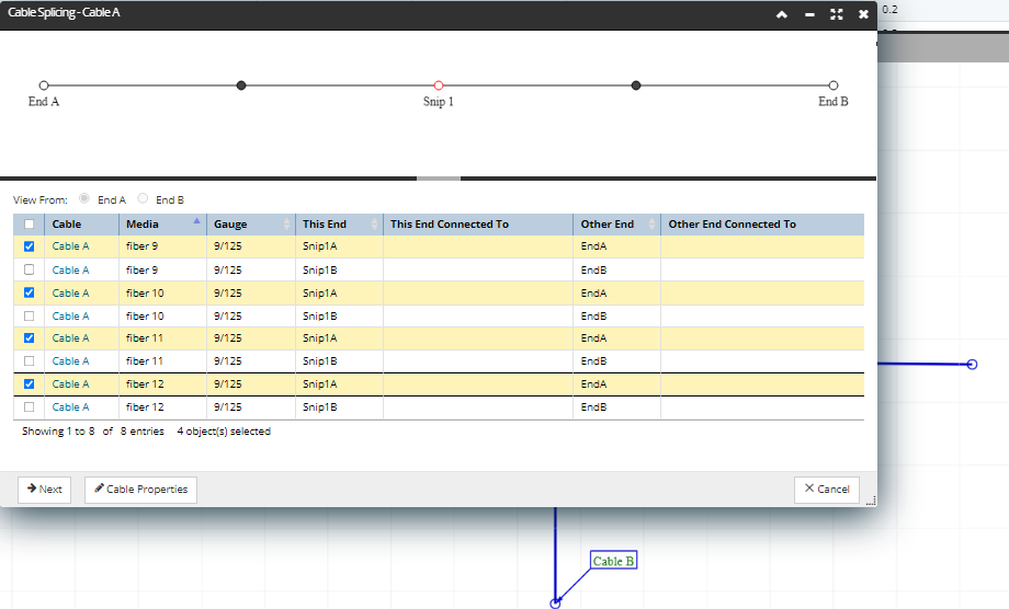
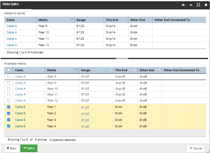
Select the Snip 1 node in the schematic top part of the dialog, as the goal is to Splice together Media 9-12 of Cable A to Cable B's Media at this Snip location. This configures the data grid on the bottom part of the dialog to list only Media Ends located at the Snip 1 point, making it easier to find the ends of the Media we're looking for.
Notice how in focus mode, the data grid shows only Media ends that are located at the selected node, Snip 1 in this case. The selected node controls what is shown under the This End column set, while the Other End column set contains whatever is at the other end of those Media segments.
According to the use case design, the last four snipped media fibers of Cable A need to be spliced to all Cable B media. To achieve this, select fibers 9-12 for the Snip1A End, as shown in the screenshot image.
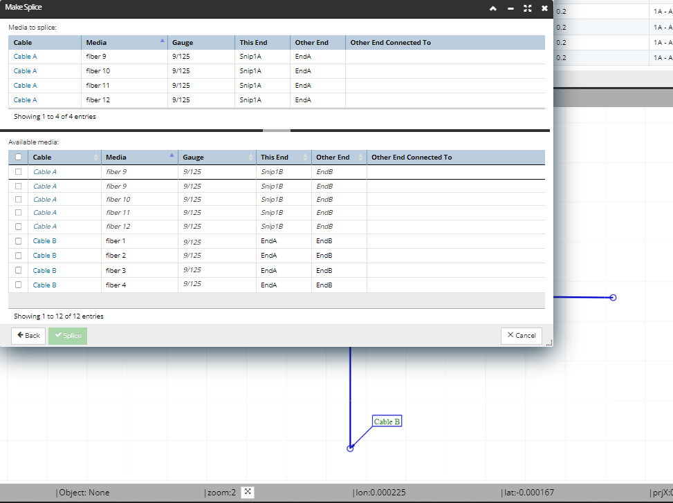
Select Cable B Media fibers to Splice the selected Cable A Media to
This is done by clicking on the checkbox icons for the associated Media rows - for our example simply select the rows with "Cable B" under the first column, as we are splicing to all four of Cable B's Media:
This activates the Splice button at the bottom - click on it to complete the Splicing operation and close the dialog.
View the results in Design World and associated Properties dialog(s)
Notice the Design World view is updated with an additional square icon at the point of the Splice, indicating that a piece of Coupler Equipment has been created as a result of the successful Splicing operation (recall that in IRM a Coupler is created even if the splice is a fusion splice):
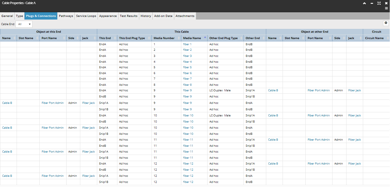
Additionally, if you look at the Plugs & Connections tab of the Cable Properties dialog for Cable A, you can observe the various Splice connections on different Cable Ends that have been created as a result of the tutorials: