This and the following subtopics are parts of a use case scenario that demonstrates Splicing and Snipping a pair of multi-Area Cables. This section only explains the layout of the expected Cable design, while the following two subsections are actual step-by-step tutorials of the Snipping and Splicing operations in the Design World.
Below is the desired layout scheme that is to be achieved as a result of the following tutorial:
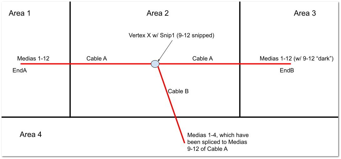
The black lines represent Area boundaries, while the red lines represent Cables
Cable A runs from Area1, through Area 2 to Area 3.
In Area 2, Medias 9-12 of Cable A are snipped (represented by the grey circle icon)
Medias 9-12 are left “dark” (unused) between Area 2 and Area 3, but those Medias (at the Snip1B Cable End) could be spliced to another cable or connected to an Equipment and therefore used again.
Cable B is created independently of Cable A, but with Media compatible with the Cable A Media
all of its Medias are spliced to Medias 9-12 of Cable A in Area 2, and it routes to another Area - Area 4.
the user can choose to consecutively splice media Cable B Media 1-4 to Cable A Media 9-12 in single splicing operation or they can create more complicated splicing by using multiple splicing operations.
Important: The following tutorials do not show the creation and routing of the Cable objects in Design World Areas, but rather assume that is already done. If you want to reproduce the exact tutorials make sure the following prerequisite actions have been completed:
a pair of Cables with compatible Media are created and placed in Design World Area close to each other
extend one End of the first Cable to another Design World Area and repeat it for the other Cable End
extend one End of the second Cable to another Design World Area
ensure the End of the second Cable that is on the same Area as the first Cable is in close proximity along the first Cable, as shown in the layout above
For more details about the associated dialogs and other user interface details, refer to the following topics: