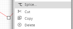
The dialog is accessed only from the Cable context menu:
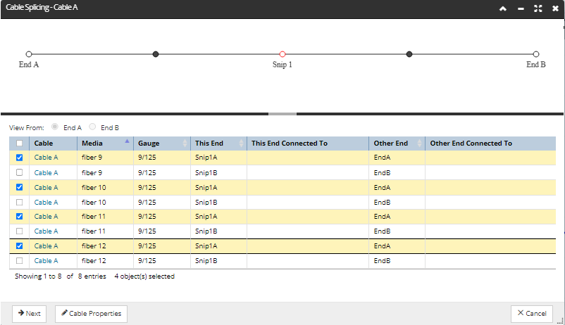
The dialog is horizontally divided into two areas: the visual panel at the top and the Media data grid at the bottom:
Visual panel
the panel displays a schematic representation of the Cable and the sequence of Snips in the Cable
Cable Ends and Snip points are represented with small transparent circle icons, or nodes, along the line that represents the Cable
if any of the nodes is selected, the data grid content gets filtered from the perspective of that selected node - which is Snip 1 in the example above
the selected node controls what is shown under the This End column set, while the Other End column set contains whatever is at the other end of those Media segments.
this allows the user to view everything that is available at that particular selected node - i.e. a technician working at a specific location who wants to see what ends are available at that specific location
conveniently, clicking on a node automatically opens the associated Design World Area in the background and centers the view to its exact location
if nothing is selected on the schematic panel, no data filtering is done in the data grid below, which means it lists all Media segments for the selected Cable
Cable Media data grid
list all Media ends at the selected point and what those Media ends are currently connected to
allows sorting by Media column, in which case the rows are sub-sorted by Cable End, flowing from End A to any Snips to End B
the data can also be sorted by End, in which case it is automatically sub-sorted on Media.
additionally the radio buttons above the data grid allow the control of the direction the data grid is by selecting one of the radio buttons above it, but this filtering option is more restrictive, as it doesn't allow Snips to be selected.
Additional buttons at the bottom of the dialog enable the user to proceed with the Splicing operation (Next), easily access the Cable Properties dialog, or Cancel the Splicing operation.
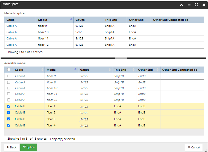
Make Splice dialog
The Make Splice dialog is also divided into two horizontal areas, both containing data grids:
the top one lists the Media selected to Splice, with column data very similar to the data grid from the previous Splice dialog (Cable Splicing)
the bottom grid lists all Media Ends available for splicing near the splice point, from any Cable, where:
the Media Material is the same
the cable gauges do not have to match to allow the cable media to be spliced.
the Media ends are not currently connected to anything
Important: Other Media ends from the same Cable are included in the list, so that it is possible to splice together the exact same Medias that were previously snipped. Notice the Media ends from the same Cable are displayed in italic font.
The Splice button at the bottom of the dialog is initially disabled (since nothing is selected to splice). To enable it, at least one row entry from the bottom Available Media data grid needs to be selected.
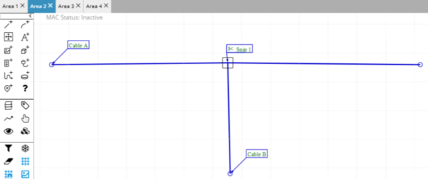
Design World Area representation of the Spliced Cable
A splice point is represented by a small black rectangle icon around it :
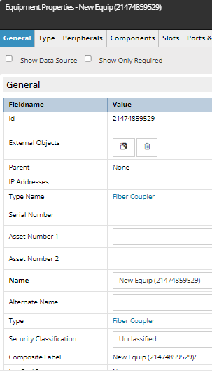
When you hover over this icon with mouse pointer, you can notice this is actually a newly created Equipment object -- a Coupler -- and as such, can be viewed as a standard Equipment object via the Equipment Properties dialog:
Note: Couplers are automatically managed by IRM during splicing operations and the user is not expected to create or delete these objects manually.