In practice, Cable splicing can be performed in different ways, depending on the Cable's media material:
Mechanical splices are made using a “coupler”, which is a simple piece of hardware such as wire nut, terminal block or cable connector
Fusion splices are accomplished by welding two fibers together
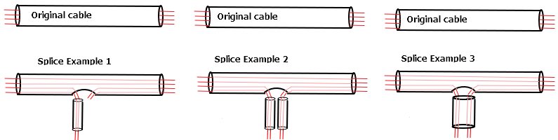
The following image demonstrates some typical splicing examples - all of these variations are supported by IRM in the same way because any Cable End, whether created originally upon Cable creation, or by snip action, can then be connected or spliced however the user desires. In other words, there is no practical difference between End A, End B, and any other ends created by snipping.
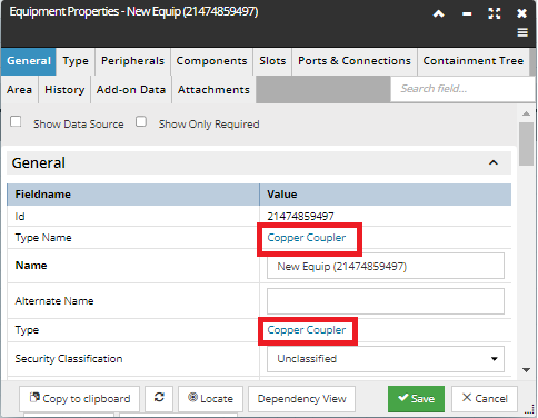
Important: To simplify the IRM design, implementation and user experience, and make them more uniform, all splices in IRM are done via the use of software couplers, including fusion splices where in reality there is no distinct coupler hardware object. In this way, we maintain the rule that all IRM cable connectivity happens through ports on equipment objects. Couplers are modeled as standard Equipment objects and are defined by the associated same-named Equipment Type. Couplers are not explicitly managed by the IRM User; rather they are automatically created or deleted by IRM upon successful Splicing operations. This implies that, if an ordinary, non-coupler Equipment is used to connect two Cable Ends to each other, this is not considered “Splicing” in IRM terms.
The following subtopic is a step-by-step tutorial that demonstrates splicing Media strands of a multi-area routed Cable and routing them to another Area, along with some user interface-related specifics and additional details of the feature.