4.3.15.2. CAD import mapping options
IRM supports the import of drawing data from CAD systems via commonly used formats supported by leading CAD vendors, such as DWG (AutoCAD), DGN (MicroStation), and DXF (interchange), file formats. IRM's CAD file import feature supports 2D drawing data only, for purposes of showing floorplans and siteplans in Areas. The process of importing CAD file data using IRM allows considerable flexibility.
The start the CAD file import process for an Area:
-
Open Area in Design World
-
Right-click in
Area Design World canvas and select
Upload CAD File from the
Area Operations Context menu.
For an overview of CAD file import, click on the following topic -
Importing CAD files. This section helps the user to understand different
CAD Import mapping options available when importing CAD files into an existing Area in the Design World.
These options help the user to:
-
efficiently re-import different versions of the same CAD file, thereby updating the data in IRM with changes made outside the system
-
use CAD file import as a convenient mechanism for creating batches of objects that are visible in the Design World, such as faceplates and various desktop equipment (computers, monitors, desktop switches, etc.)
-
in addition to creating batches of objects, the created objects can have data fields set based on information in the CAD file block instances
The following use case covers a CAD file import example, with more emphasis on the import mapping options (steps 2-4 of the Wizard) than the linked topic above.
Step 1: Selecting and uploading files for import
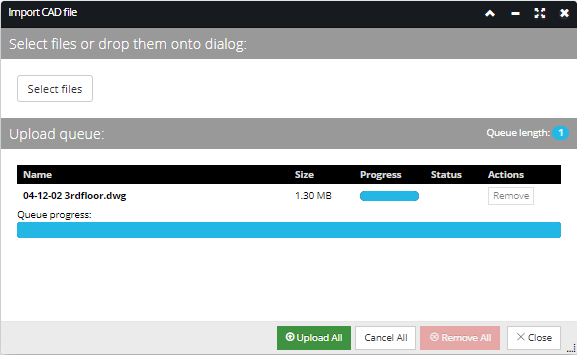
After selecting the Upload CAD file... option from the context menu, select the files to import by clicking on the Select files button, which opens a (browser) file chooser enabling a CAD file (.dxf, .dwg, .dng) to be selected for import. Once the file is selected it is displayed in the Upload queue grid, along with its Size, upload Progress and Status.
In this example a single file is selected - 04-12-02 3rdfloor.dwg. Once the Upload All button is clicked the file is uploaded to the server for processing. The application validates the file as a supported CAD file and prepares the file to be imported into the Area by creating the set of temporary objects (Layer, Line and Block objects) needed for the following steps. If these operations finish without an error, the next step of the wizard is displayed.
Click on the Upload All button to upload the selected file to the server so that they can be imported into the selected Area:
For a detailed use case scenario of a CAD file import, click on the following topic -
Importing CAD files.
Step 2: Layer Mapping
This step allows the user to control how layer styles and layer content in the Source Layers will be imported by:
-
mapping the source layer to an existing Area layer.
-
creating source layer as new layer definition.
-
overwriting an existing layer with the source layer styles.
-
overwriting an existing mapped destination layers content with the source layer content.
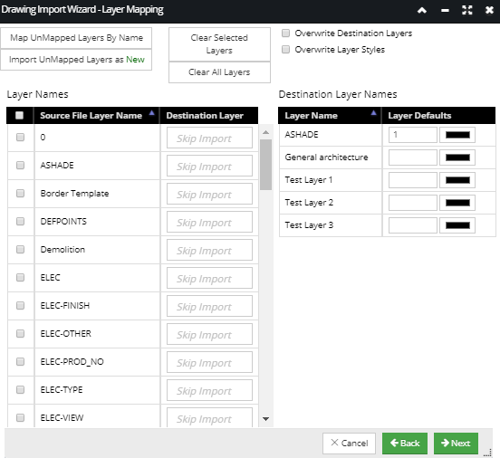
The screenshot below displays the Drawing Import Wizard - Layer Mapping step for the uploaded file, with all import properties and mapping options contained set as blank or default value(s):
In this example we selected a CAD file that contains a floorplan for a certain building - 04-12-02 3rdfloor.dwg. In general, this wizard step is divided into 2 parts: the left (source) section and the right (destination) section, both containing data grids and several additional buttons and checkboxes for applying special mapping options. The left side grid (Layer Names) displays Layers from the source file listed by their Layer Name, with the blank text boxes reserved for specifying a Destination Layer. Similarly, the right side grid (Destination Layer Names) displays Layers that already exist in the Site by their Layer Name, together with some default Layer settings.
The left Source Layers grid enables several selection modes:
-
single row selection - single left mouse click on the row entry
-
multiple individual row selection - hold CTRL key + left mouse click on the row entry
-
multiple consecutive row selection - single left mouse click on the starting row entry and hold SHIFT key + left mouse click on the ending row entry
-
toggle selection of all rows - click on the checkbox in the header row
In addition, in the case of multiple selected rows, individual row(s) can be deselected individually by a single left click on the row.
The main purpose of this step is to define which Source Layers will be mapped to which existing Destination Layers in the selected Area. This can be done automatically, by clicking on some of the buttons above the grid, or manually, selecting row(s) in the Source and the Destination grid.
The following is a use case scenario of completing Layer Mapping step using auto-map options:
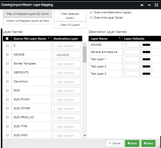
To automatically map any currently unmapped source Layer(s) to destination Layers of the same name(s), name click on the Map UnMapped Layers By Name button. This option is typically chosen when a file that had been previously imported is being re-imported (presumably an updated version of it), as in that case the layers will already exist in IRM. The layer will inherit layer attributes from the source layer i.e. Name, Color, weight, etc. if the Overwrite Layer Styles option is selected.
In our example there is an existing Layer with the same name in the selected Area - ASHADE that is automatically set as Destination Layer once the Map UnMapped Layers By Name button is clicked:
Note: This mapping will only be applied to the Source layers where no Destination layer is currently set.
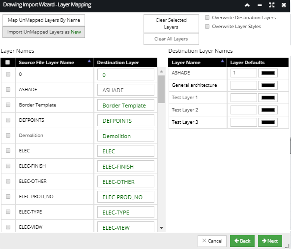
To automatically map the remaining un-mapped Layer rows, simply click the Import UnMapped Layers as New button. This creates a new Layer in IRM for each previously unmapped Source Layer. This option is typically chosen when a file is being imported into IRM for the first time, as in that case the needed layers will likely not yet exist in IRM. In this example, there are currently no existing Destination Layers that correspond to the remaining Layers in the Source file Layers list so, after Import UnMapped Layers as New, is clicked, the Destination Layer column shows all the layers that will be created in a green font:
When operating this dialog, it is very common to first click Map UnMapped Layers By Name and then immediately click Import UnMapped Layers as New. This will cause existing Layers to be mapped and the remaining Layers to be created, which is ordinarily what is needed. Alternatively, manual control of the mapping can be taken, as described below.
Layers can also be mapped manually by selecting the source layer(s) by clicking on the checkbox next to the appropriate Source File Layer Name and then selecting the destination layer by clicking on the appropriate row entry in the Destination Layer Names grid. The existing Destination Layer is also enabled for selection simply by typing the first letter of the layer name in the Destination Layer field that provides a filtered drop down list of result matching the entered criteria. Once the destination layer is selected it will set the Destination Layer column to the selected destination Layer:
Set Overwrite options by clicking on the appropriate checkbox to specify whether the existing destination layer content and/or styles are being overwritten by the newly imported source Layer content / styles.
To have the contents of the destination layers overwritten by the mapped source file layer content, click on the Overwrite Destination Layers option checkbox. This will have all mapped destination layer objects (i.e. lines, arcs, and text) in the Area first deleted and then each mapped Layer is populated with the new objects from the file being imported. When this option is unchecked, the imported objects are simply appended to any existing objects in the destination layers.
To have the destination layer's style overwritten by the mapped source file layer styles, click on the Overwrite Layers Styles option checkbox. This will replace all destination Layer attributes with the layer attributes taken from the layer being imported.
In other words, the former option controls whether the graphical objects (lines, arcs, and text) are updated, whereas the latter option controls whether the layer properties are updated. In our example, we will have both checkbox options unchecked, as we want the new Layer objects be created in addition to existing ones, same as for Layer Styles.
Step 3: Replace Blocks with Equipment Types
Normally, a CAD file import operation creates only lines, arcs, text and block shape objects, but this feature enables the user to replace basic CAD Block instances in the imported CAD file with fully defined Equipment objects in the destination Area.
This can be useful, for example, in cases where a CAD file contains faceplate or rack/cabinet positions as block instances. In this way, IRM users can replace the Blocks with actual Equipment Types, allowing a simple Block Shape to become a complex Equipment object containing Product Data, Dimensional Information, Port and Connector data, etc.
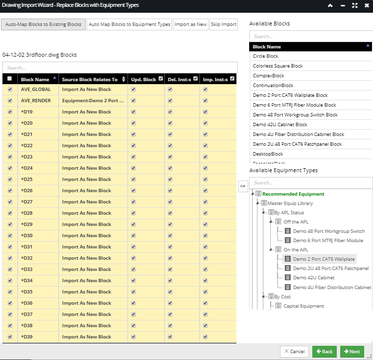
Step 3 of the CAD Import Wizard - Replace Blocks with Equipment Types enables the user to specify which block(s) should be replaced by which Equipment objects.
The following screenshot displays the next step of the CAD Import Wizard for our use case scenario, with the screen displaying the default properties set for this step:
To understand all the features provided by this dialog in this step we will review first the main parts of the dialog. It is, similarly to the previous step, arranged in 2 main sections:
-
the left section contains:
-
several buttons that enable additional features to this import step, as explained in the following text by examples
-
a read-only text label displaying the original source CAD file name
-
the list of all Blocks detected by IRM in the source .dwg file with additional checkbox controls organized in a data grid, and with an additional Quick Search control above it
-
the right section contains:
-
the list of
Available Blocks in IRM, with a Quick Search control above it
-
the list of
Available Equipment Types in IRM, with a Quick Search control above it
The default state of the dialog (upon dialog's entry, as displayed in the screenshot above), is as follows:
-
all
checkboxes under the first column are selected
-
blocks are auto-mapped to existing blocks by name and any blocks that aren't mapped are set to
Import as New Block -
all option
checkboxes in column headers are checked
These defaults work well in the most common cases where the imported CAD files:
-
contains entirely new Blocks shape definitions that do not currently exist.
-
updating existing block shapes with new block shape definitions
-
updating any changed Block shape definitions and replacing any previously imported Block Shapes
The main parts of the left side grid (referred to as the "Source Grid" in the following text) are as follows:
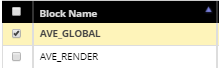
- This column gives the name of the Block as it occurs in the source CAD file
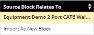
- This column describes how Blocks in the source file relate to existing blocks or to Equipment Types.
In addition, the following restrictions are applied:
-
if this field is set to
Skip Import (by selecting the row entry and clicking on the Skip Import button), the 3 update options in the column headers (discussed below) are all disabled
-
if this field is set to
Import as New (by selecting the row entry and clicking on the Import as New button), then
Update Block and
Import instances are checked and
Delete Instances is unchecked
-
if the relation is either a
Block or
Equipment Type mapping, the following 3 update options in the column headers are all enabled
The checkboxes at the beginning of these column headings are checked by default, indicating the following:
-
Update Blocks - this column says whether or not to change the destination block object itself
-
Delete Instances - this column says whether all instances of the mapped (destination) Block Shapes or Equipment objects should be deleted before new objects are imported
-
Import Instances - this column says whether new instance objects (Equipment or Block Shapes) should be created
While the default mappings work well in many cases, additional auto-map / auto-import buttons are available to help tweak the block mappings.
All of them work on selected rows only:
-
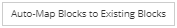
- automatically maps the selected Block(s) to existing Block(s) by name
-
- automatically maps the selected Block(s) to Equipment Type(s) by name
-

- sets the selected row(s) to Import as New
-

- sets the selected row(s) to be skipped during Import
Similarly to the previous wizard step, the grid in this step also enables several selection modes:
-
single row selection - single left mouse click on the row entry
-
multiple individual row selection - hold CTRL key + left mouse click on the row entry
-
multiple consecutive row selection - single left mouse click on the starting row entry and hold the SHIFT key + left mouse click on the ending row entry
In addition, in case of multiple selected rows individual row(s) can be deselected individually simply by a single left clicking on the row.
-
toggle selection of all rows - click on the checkbox in the header row
In our example file, there is a quite long list of Blocks detected by the CAD Import Wizard, all of which are displayed and by default selected in the left-side grid. If a row entry is checked, which happens by default, the Block Instance will be imported, while if it's unchecked it will be skipped in the import operation. Similarly to the previous step, the mapping options in this step can also be specified automatically or manually.
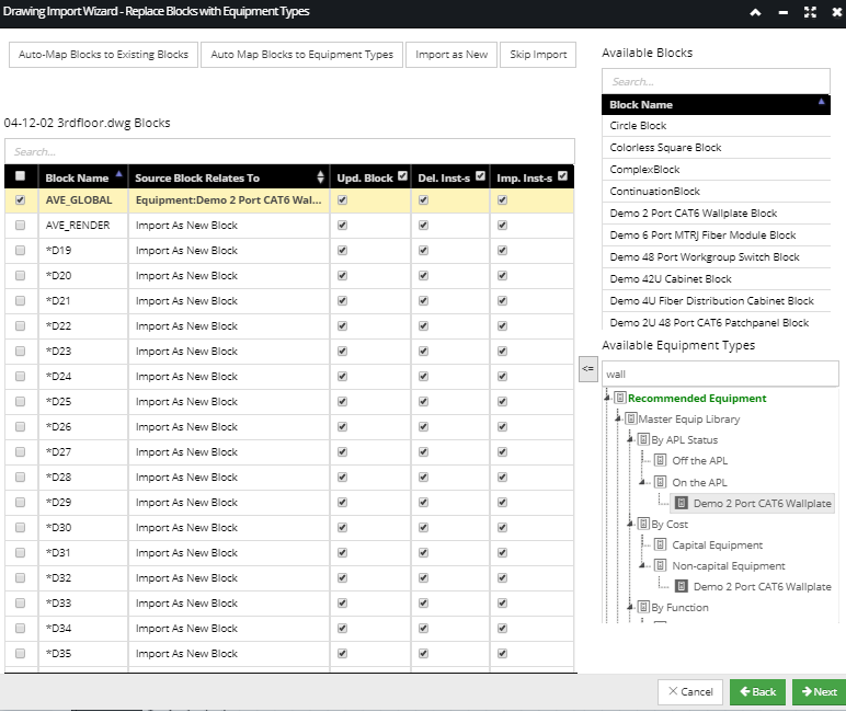
A source CAD block can be manually assigned to an existing Equipment Type by first selecting the Block entry from the Source Grid and then by selecting the corresponding Equipment Type entry from the Available Equipment Types tree and clicking the assign button (<=) between the two sections. The Quick Search feature enables users to apply additional filtering of the Available Equipment Types tree by simply typing in the name (or part of the name) in the Search... text field above the tree, which displays a filtered tree matching the (partially) entered name:
Similarly, an imported block can be manually assigned to an existing Block by first selecting the Block entry from the Source grid and then by selecting the corresponding entry from the Available Blocks list and clicking the assign button between the two sections. The Quick Search feature enables additional filtering of the Block list by simple typing in the name (or part of the name) in the Search... text field above the list.
Note: If CAD file import would create duplicated objects via Block mapping and the Clear Existing Instances option is not selected and Import Instances is selected, an error results and the instances are not created.
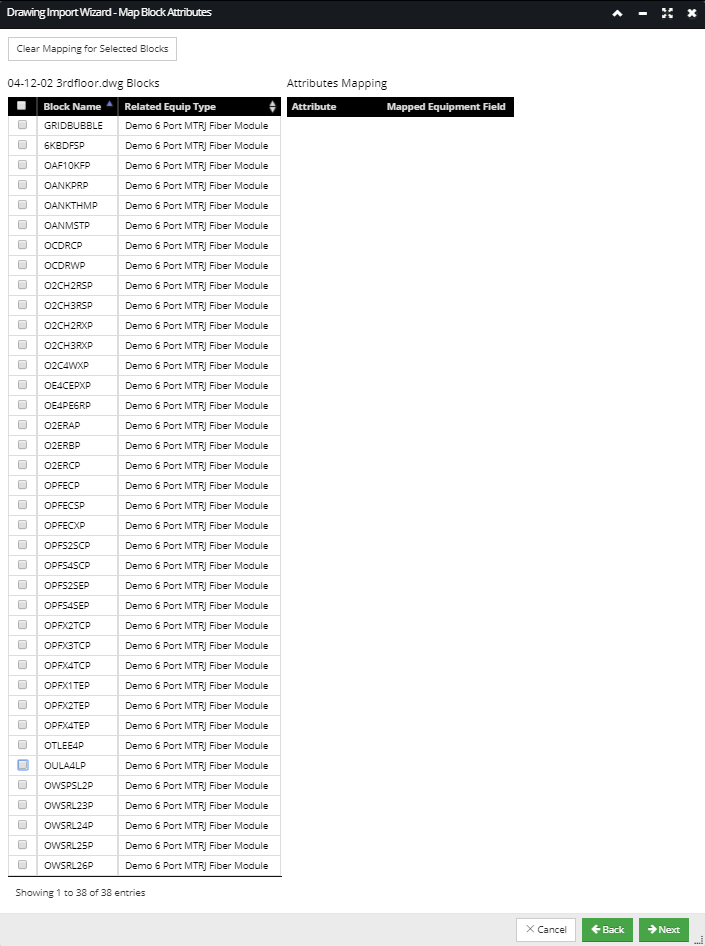
Step 4: Block Attribute Mapping
The Map Block Attributes dialog, enables using source block attributes to set fields in corresponding Equipment objects.
The default state of the dialog (upon dialog's entry, as displayed in the screenshot above), is as follows:
-
none of the checkboxes under the first column in the left grid are selected
-
no mappings are specified for mapping Block Attributes
To understand all the features provided by this dialog, we will review first the main parts of the dialog. It is, similarly to the previous wizard step, arranged in 2 main sections:
-
the left section contains
-
the
Clear Mapping for Selected Blocks button (explained in the text below)
-
a read-only text label (the original source CAD file name + "Blocks")
-
a grid listing Source Blocks that have attribute data defined and/or are mapped to an Equipment Type in the previous step, referred to as the "Mapped Blocks" grid later in this section
-
the right section contains
-
the list of all
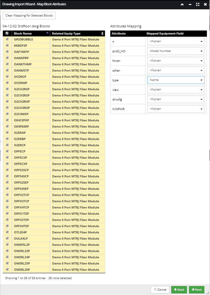
Block Attributes and the mapped field, associated with the row currently selected in the Mapped Blocks grid:
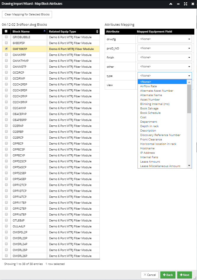
The list of Blocks displayed in the Mapped Blocks grid represents the list of source Block instances specified to be mapped to existing Equipment Types in the previous Wizard step, each of which is displayed in the Related Equip Type column in the Mapped Blocks grid. In this example, the selected Block displays six block attributes, each listed by their original name as a separate row entry in the (right) Attributes Mapping grid. Clicking on the drop down menu under the Mapped Equipment Field for a selected row entry displays a list of available fields associated with the specified Equipment Type that the selected Source Block instance will be replaced with.
Similarly to other grids throughout this Wizard, all row entries in the Mapped Blocks grid can also be selected, simply by clicking on the checkbox in the table heading. This is useful in cases like this example, when all Source Block instances are mapped to the same Equipment Type in Step 3 of the CAD Import Wizard.
In this example, only 2 Source Block Attributes are being mapped to Equipment Type fields - proD_NO to Model Number and type to Name:
Because the rest of the block attributes are left unmapped, they are discarded from the import operation. If a specific mapping needs to be removed, clicking on the Clear Mapping for Selected Blocks button removes the mapping for the selected Source Block row entry in the left grid.
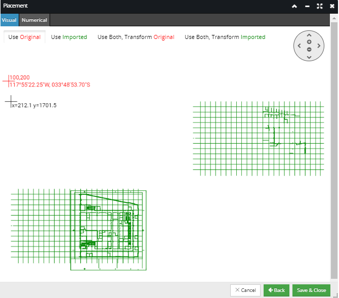
Step 5: Placement
The last step of the CAD Import File Wizard, the Placement dialog contains 2 tabs - Visual and Numerical. These tabs allow the user to position the newly imported drawing data in relation to existing drawing data in the Area.
The Visual tab displays the selected Area drawing canvas, which is zoomed out by default to the extents of all objects currently defined in the Area, or to a zoom level that shows the entire imported drawing.
The screen displays the graphical alignment view, where the new data can be positioned with respect to the existing data (assuming there is any existing data):
The Placement screen also contains a radio button set that is common to both tabs and allows the following 4 options regarding the coordinate system to use for the import:
-
Use Original - Use the existing (red) coordinate system in the Area and transform (by x,y translation) the newly imported (green) coordinates according to the positioning given in the placement window (use red, transform green). Under this option, the Area will be left using the same coordinate system it had before the import operation. Use this option only for non-geo coordinate systems.
-
Use Imported - Use the newly imported (green) coordinate system and transform the existing (red) coordinates according to the positioning given in the placement window (use green, transform red). Under this option, the Area will be left using a new coordinate system created as part of the import operation. Use this option only for non-geo coordinate systems.
-
Use Both, Transform Original - This option requires both coordinate systems to be geo coordinate systems and is useful when the datums for the two coordinate systems are different. Use both anchors and use the newly imported (green) local coordinate system, so the existing (red) local data gets transformed into the new (imported) coordinate system (use both anchors, transform red local). The difference between this option and "Use Imported" is that for this option the system transforms the existing data into the new coordinate system and then applies the translation specified in the dialog, whereas for "Use Imported" it simply applies the translation directly on the existing data, essentially assuming that the two coordinate systems were "compatible" in the first place.
-
Use Both, Transform Imported - Similar to "Use Both, Transform Original" but using the original coordinate system instead as the target. Use both anchors and use the existing (red) local coordinate system, so the newly imported (green) local data gets transformed into the original coordinate system (use both anchors, transform green local).
The Numerical tab displays the details of the Anchor Points (both the existing and new anchor points) and allows values to be entered for them:
Save the CAD Import settings and complete the CAD file import
Clicking on the Save & Close button saves the selected CAD Import parameters, closes the CAD Import Wizard dialog and opens a full screen animation overlay, which indicates the actual start of the drawing import. Progress is indicated with a spinner and the percentage of the import completed. After completion, the newly imported drawing file is loaded and displayed in the previously opened Area (canvas).