Upon the Create Maintenance Hole button click the created Maintenance Hole object is locked to the mouse cursor, which changes its appearance from arrow to crosshair. The object can be dragged around the Canvas in the Design World and its location is set with a single left click at the desired position.
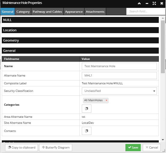
The created Maintenance Hole object is given default property values, which can be changed in the Maintenance Hole Properties dialog:
This dialog is accessed by selecting the Edit Properties... option from the Maintenance Hole's context menu.
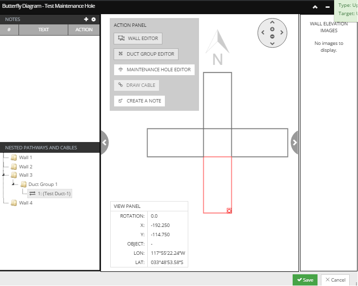
In the Butterfly Diagram, click on a Wall enables the Wall Editor button located in the Action Panel.
Click on the button opens the Wall Editor dialog for the selected W3 Wall:
The dialog displays basic properties of the selected Wall, such as Wall Number, Depth and Length, along with an additional Add a Duct Group button that enables adding an additional Duct Group.
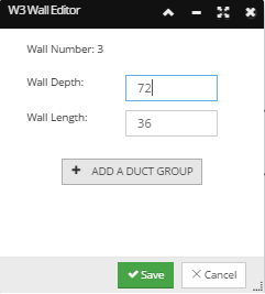
The default parameters are already set in the Duct Group Editor, but can be changed. Since in this example a single Duct is being connected to the created Maintenance Hole, the displayed parameters with remain the same.
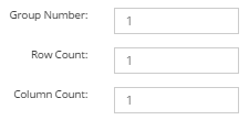
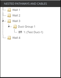
Click on the Save button creates the Duct Group and displays it both in the central Butterfly Drawing:
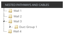
and in the Nested Pathways and Cables tree:
These changes have to be saved by clicking on the Save button in the bottom of the dialog, which closes the Butterfly Diagram dialog and brings focus back to the main application screen.
Click on the Create Pathway button in the Design World toolbar opens the Create New Pathway sub-dialog. It enables creating single and multiple Pathway instances of the same or different Pathway Type and drawing them in the Design World.
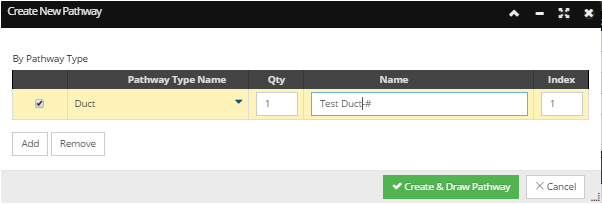
Set the parameters for the new Pathway in the Create New Pathway sub-dialog. This dialog enables creating single and multiple Pathway instances of the same or different Pathway Types and directly drawing them in the Design World upon creation. It displays a grid that lists Pathway entries of the same Pathway Type.
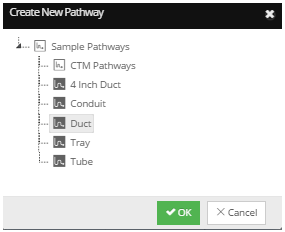
The first step in configuring a new Pathway is setting the Pathway Type. Click on the arrow icon under the Pathway Type Name column opens a sub-dialog that displays categorized Pathway Types in a tree menu structure:
Once a selection is made, the OK button is enabled and clicking on it closes this sub-dialog and brings focus back to the Create New Pathway sub-dialog. Since the goal of this use case is to show how Pathways are connected to Maintenance Holes in the Butterfly View, the Duct Pathway Type needs to be selected. The reason behind this is that the Butterfly View enables managing only top-level duct Pathways, as compared to inner ducts, trays, and ladders. However, in general, all Pathway Types are supported for drawing in the Design World.
For more details about Pathway objects in general, see the following topic and its sub-topics - Pathway Management.
For this example, the Quantity parameter is set to 1, as well as Index, since a single duct is being connected to the created Maintenance Hole. After all parameters are set, click on the checkbox under the far left column and then click on the Create & Draw Pathway button closes the Create New Pathway dialog and brings focus back to the main application screen.
Draw the newly created Pathway in the Design World
Once the Create New Pathway sub-dialog is closed, when the mouse cursor is over the Design World area it changes its appearance from arrow to crosshair, indicating it's in drawing mode. A single left click on the desired position sets the starting point of the new Pathway object. The next single left click sets the second point of the new Pathway, and so on.
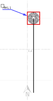
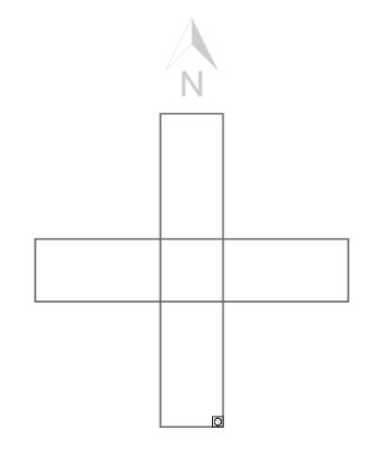
Once the Pathway is routed to the desired location, the drawing operation can be finished with a double left click at the position of the final point:
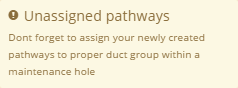
After the duct is drawn in the Design World, it can be connected to the previously created Maintenance Hole via the Butterfly View dialog, which is also indicated with a warning message that pops out in the top-right corner of the screen:
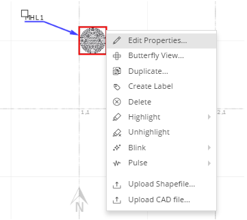
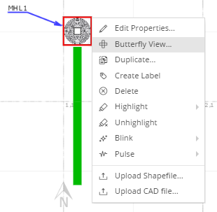
The first step in assigning a Duct to the Maintenance Hole is to select the Maintenance Hole in the Design World by a single left click. The next step is to right-click on the Maintenance Hole object and select the Butterfly View... option from its context menu:
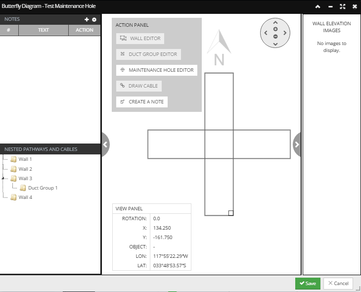
This opens the Butterfly Diagram dialog and displays the previously created Duct Group, both in the central Butterfly Drawing area and in the Nested Pathways and Cables tree menu:
Once in the Butterfly View, select the previously created Duct Group.
This can be done in two ways:
click on the Duct Group in the central Butterfly Drawing and click on the Duct Group Editor button in the Action Panel
click on the Duct in the Nested Pathways and Cables tree menu and click on the Duct Group Editor button in the Action Panel.
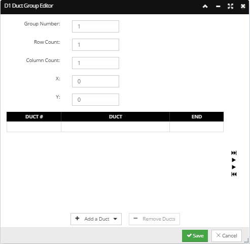
This opens the Duct Group Editor sub-dialog, that enables editing Duct Groups and managing (i.e., adding, editing, removing) top-level Duct Pathways and Cables:
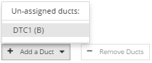
In the Duct Group Editor dialog, clicking on the Add a Duct button opens a pop-out menu displaying a list of un-assigned Duct instances. In this example, End B of the previously created duct is available for assignment and is displayed in this list.
Click on it adds the selected duct to the grid:
Click on the Save button closes the sub-dialog and brings focus back to the main Butterfly Diagram dialog, displaying the newly assigned duct both in the central Butterfly Drawing area;
as well as in the Nested Pathways and Cables tree:
These changes have to be saved by click on the Save button in the bottom of the dialog, which closes the Butterfly Diagram dialog and brings focus back to the main application screen.