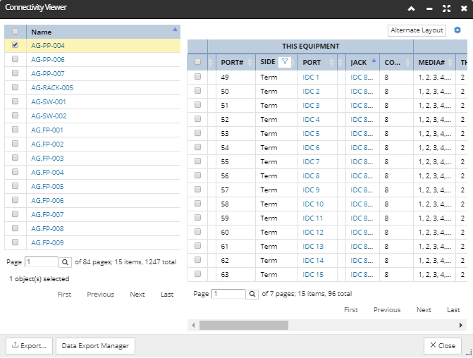
The Connectivity Viewer enables viewing and exporting Cable connectivity information for a set of Equipment objects from a single dialog.
The dialog is opened by clicking a dedicated button in the function bar above the Object Grid, which is active when the Equipment Object Grid tab is selected.
Both the appearance and functionality of the Connectivity Viewer dialog are very similar to the Equipment Properties Ports & Connections tab, but with the following differences:
The dialog consists of two parts - a simple grid listing Equipment by its name on the left and the Port & Connections grid on the right. This allows selecting single or multiple Equipment objects from the left grid and displaying ports from these Equipment objects in the right grid.
Ports from more than one Equipment object can be shown in this dialog. The dialog shows the Ports from the current set of Equipment objects listed in the Object Grid (the full set of Equipment in all pages, with current filters applied, if any).
This dialog does not allow Cable connections to be made or broken, only viewed.
While the dialog is opened, any selection of Equipment in the Object Grid, whether single or multiple, will select the same Equipment in the left side grid in the Connectivity Viewer dialog. The same goes the other way - selecting a row in the left grid in the Connectivity Viewer automatically selects the row for the same Equipment in the Object Grid.
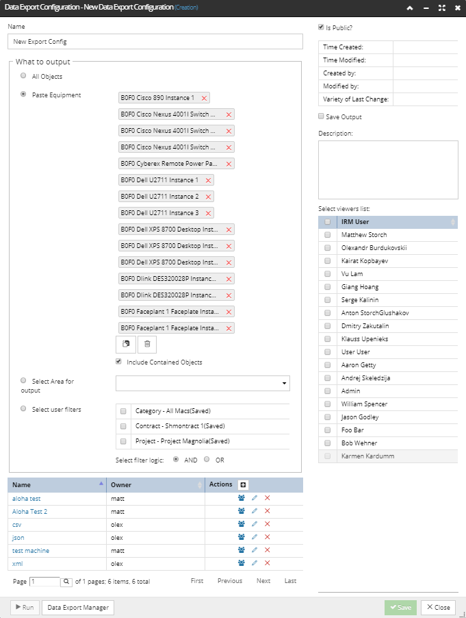
Notice the two additional buttons at the bottom of the dialog - the second one opens the Data Export Manager dialog, while the first one opens the Data Export Configuration dialog, with the "What to Output" section predefined:
The Paste Equipment radio button is selected by default and Equipment objects from the first page in the object grid are pre-added.