IRM allows the user to trace physically connected sequences of Equipment and Cables via the Path Trace feature. This feature is useful for understanding the connectivity between Equipment objects and also for defining Circuits.
A Physical Path Trace operation results in a sequence of connected path steps based upon Equipment Port and Cable connectivity. This sequence is treated as a single path trace entity and cannot be broken up; that is, other Path Steps cannot be inserted into the middle of it, nor can individual Path Steps in the sequence be deleted. The sequence of Physical Path Steps can be used as a starting point of a Circuit, or can appear within a larger sequence of Path Steps of different varieties (Virtual Path Steps, Bearer Path Steps, and Branching Path Steps).
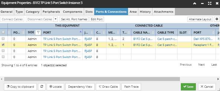
A Path Trace can be initiated from the Ports & Connections tab in the Equipment Properties dialog via the Path Trace button, which is active when one or more Ports (rows) are selected:
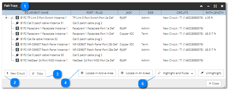
Clicking that button opens the Path Trace dialog, which has a main grid that looks very similar to the grid we use for showing Circuit Path Steps in the Path Steps tab in the Circuit Properties dialog. The following screenshot images and text explain the dialog in more detail:
Path Trace grid
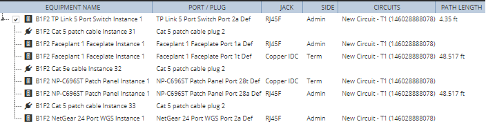
The Path Trace can contain multiple root-level items, which is what happens when the Path Trace is invoked and multiple Ports are selected. In this example, a single selected Port from the B1F2 TP Link 5 Port Switch Instance 3 is added.
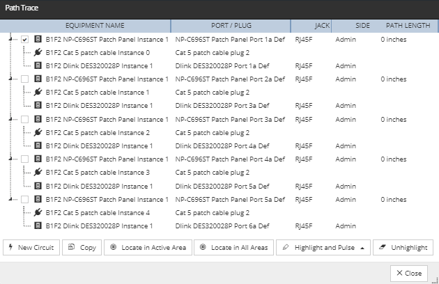
If Multiple ports are selected for Path Trace the Path Trace Grid will create a branch for each selected Port:
The above diagram, shows multiple Ports from the Patch Panelare added, the resulting Path Trace dialog and displays the Path Step sequences within each port.
This button creates a new Circuit and adds the currently-selected Path Traces to it. If multiple Path Traces are selected, it will create a new Circuit with multiple root level nodes.
This button puts the selected Path Traces on the IRM Clipboard. The Paste Path Trace button in the Path Steps tab of the Circuit Properties dialog allows the trace to be added to an existing Circuit. The user can select multiple nodes. If the copied Path Trace is pasted it into an otherwise empty Circuit, the resulting Path Trace grid will look exactly the same as this Path Trace dialog. If the targeted Circuit contains existing Path Steps, it will create a single level branching Path Trace for the selected Path Step sequence.
The Locate in Active Area button highlights any part of the selected Path Trace that lies within in the currently active Area, if any. This feature supports multiple selection.
The Locate in All Areas button highlights the selected Path Trace, opening any additional Areas needed in the Design World.
colors the entire Circuit path in the Design World with the specified highlight color. Click on it opens a drop-down menu for selecting between different highlight states.
Note: Color for each highlight state is specified under the Global Settings.
This button un-hilights any objects that were previously highlighted by the Locate or Highlight buttons.