Start Path TraceThis operation adds a new Path Step sequence to the Circuit.
Conditions for enabling the button:
-
any clipboard content that indicates a potential physical Path Step, i.e. an Equipment object -
Result:
-
Circuit gets a Path Step sequence populated by the path trace operation
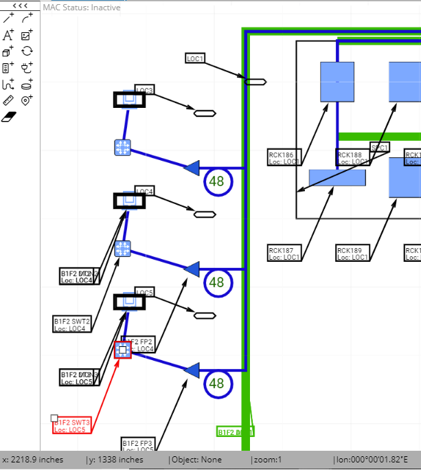
For convenience in this example, the Path Trace for the newly created Circuit instance Test Circuit 1 will consist of the existing objects in one of the Areas, displayed in the screenshot image below (in red):
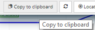
A Circuit's Path starts at a Port of some Equipment and continues along a sequence of Cable/Plug, Port, Cable/Plug, etc. For this example, one of the existing (connected) Equipment objects from an existing Area will be selected to start the Path Trace (shown in red above). The first step is to copy that Equipment to the Clipboard, by clicking on the Copy to Clipboard button on the bottom of the Equipment Properties dialog:
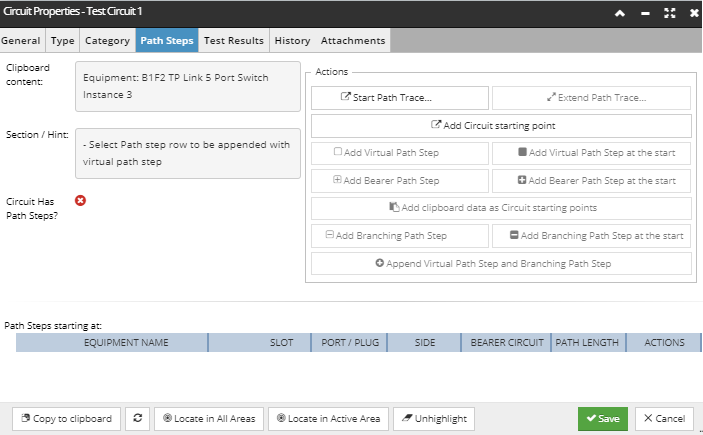
Copying the item to the clipboard causes the Clipboard content text box in the Circuit Properties - Path Steps dialog to be updated automatically, and will also cause the Start Path Trace... button to be enabled.
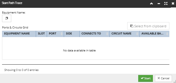
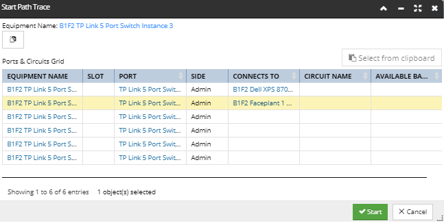
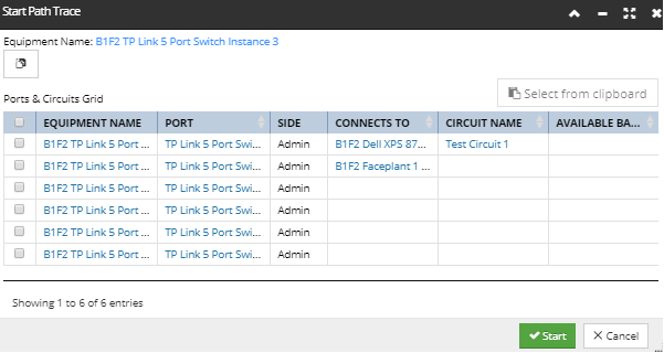
Clicking on the Start Path Trace... button opens the Start Path Trace dialog, which is initially empty, displaying only the Paste from Clipboard button (Equipment Name) and the empty Ports & Circuits Grid, as displayed below:
Clicking on the Paste from Clipboard button (Equipment Name) causes the grid to be populated with the list of Ports from the pasted equipment:
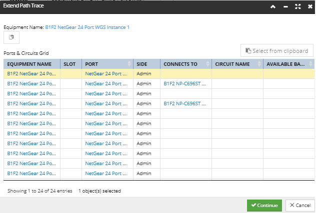
This displays the Equipment Name as a hyperlink for quick access to its Properties dialog, as well as the Ports & Circuits Grid, which lists all Ports for the selected (pasted) Equipment. In addition to Equipment Name, the grid also lists
-
all Ports associated with the selected Equipment, both on the Equipment object itself and on any cards/modules in the Equipment's Slots -
the Slot that holds the card/module each Port is on, if any -
the Side (Admin or Term) that the Port is on -
Equipment on the other side of the Cable that Connects To this Equipment's Port -
the existing (bearer) Circuit a Port is assigned to, if any, and its Available Bandwidth
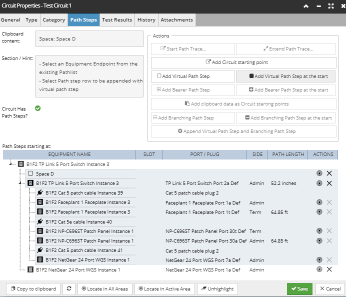
Selecting one of the rows tells IRM which Port the Path Trace should be started from and also enables the Start button at the bottom of the sub-dialog. Clicking that button executes the Path Trace, closes the sub-dialog and brings focus back to the Circuit Properties - Path Trace dialog, which displays an updated Path Steps grid with the results of the trace:
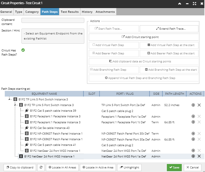
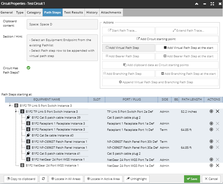
The Path Steps grid displays the following information:
-
Object Name, since the Path Step can be one of the following types of objects: Equipment, Cables, Areas, Pathways, Racks, Locations and other Circuits -
Slot Name, when the Port is on a child card or module
-
Port Definition Name or Plug Definition Name, depending on whether the row entry is Equipment or Cable.
-
the Side of the connected Equipment Port -
name of any existing Bearer Circuits specified for any of the objects included in this Circuit's Path Trace -
the Path Length of the traced Path Step
In addition, the Actions column contains two buttons - Locate and Remove. Note that the Remove button removes the currently selected row entry, as well as any associated path steps if a physical trace is selected. The button is disabled for Path Steps that are a part of a Physical Path Trace sequence, as such a sequence is either all included or not included at all. That is, the Circuit cannot contain only a part of a Physical Path Trace.
In case a Bearer Circuit is assigned to the selected Port, a single row would be populated in the resulting Path Steps grid, but since this is not the case in this example, the Path Steps grid is populated with the selected Port, as well as all other objects connected to it via Cables and internal equipment links.
Note how the complete connection Path from the selected Switch Equipment is traced:
-
starting from the selected Port 2a on the starting Switch Equipment, -
which has a Cat 5 patch Cable connected by its Plug 2 -
followed by another Equipment, a Faceplate, connected to its Port 1a -
Port 1a on the Admin side of the faceplate is linked to Port 1t on the Term side
-
a plant cable runs from Port 1t on the faceplate to Port 30t on a patch panel -
Port 30t on the patch panel is linked to Port 30a
-
a patch Cable connects Port 30a to Port 7a on a workgroup switch
|