4.3.11.3. Routing Circuits
In IRM, Circuits are used to define end-to-end service paths across the network infrastructure, by identifying active ports, used media and bandwidth, as well as visualizing the route.
IRM supports two type of circuits:
-
physical (physical path) and -
virtual (logical path), as well as a combination of the two.
Physical circuits are used to identify specific paths through equipment, ports and media, whereas virtual circuits are generally used to define and manage WAN circuits or virtual circuits where limited information is known about the physical path of the circuit. A logical path is typically used to identify network paths provided by third parties such as an ISP or carrier.
A Path Step represents a single point-to-point link in a Circuit. Like a Circuit itself, a Path Step can either be physical, where it indicates a specific Port (or even specific connection points in a Port), or virtual, where it indicates a device or Location that the Circuit goes through without consideration of the exact details.
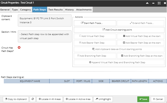
The central place for configuring and managing Path Steps is the Path Steps tab in the Circuit Properties dialog. The tab allows the user to create and modify Path Step sequences, which are set based on:
-
the Clipboard content, which is listed in a separate text box in the top left -
the current selection, which is also listed in the text box below the one for the Clipboard content -
the current Path Step configuration, which is listed in a data grid in the bottom half of the dialog, along with the main properties of each Path Step
The following screenshot images and text explain a use case of adding a combination of physical and virtual Path Steps to the Circuit instance Test Circuit 1, created previously in topic - Creating Circuits .
 Start Path TraceThis operation adds a new Path Step sequence to the Circuit.
Conditions for enabling the button:
-
any clipboard content that indicates a potential physical Path Step, i.e. an Equipment object -
Result:
-
Circuit gets a Path Step sequence populated by the path trace operation
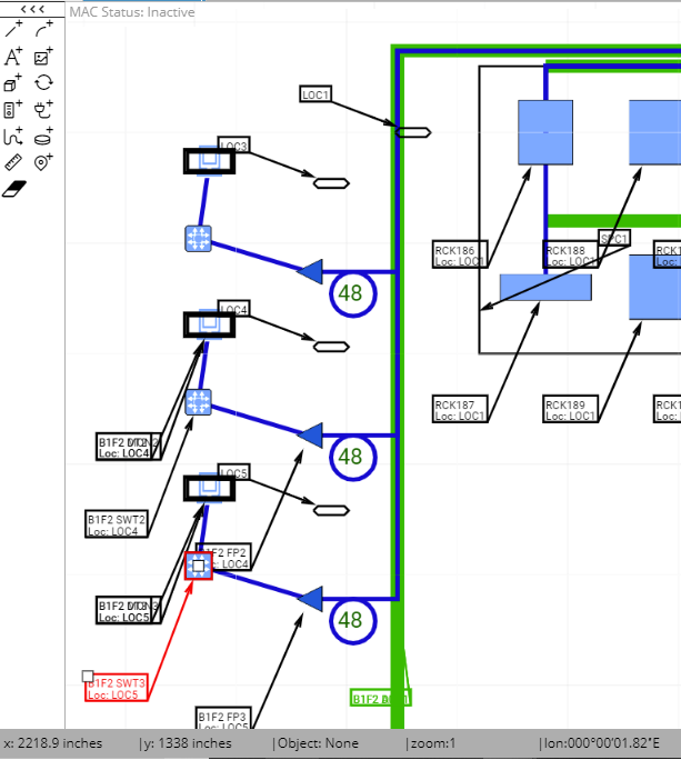
For convenience in this example, the Path Trace for the newly created Circuit instance Test Circuit 1 will consist of the existing objects in one of the Areas, displayed in the screenshot image below (in red):
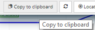
A Circuit's Path starts at a Port of some Equipment and continues along a sequence of Cable/Plug, Port, Cable/Plug, etc. For this example, one of the existing (connected) Equipment objects from an existing Area will be selected to start the Path Trace (shown in red above). The first step is to copy that Equipment to the Clipboard, by clicking on the Copy to Clipboard button on the bottom of the Equipment Properties dialog:
Copying the item to the clipboard causes the Clipboard content text box in the Circuit Properties - Path Steps dialog to be updated automatically, and will also cause the Start Path Trace... button to be enabled.
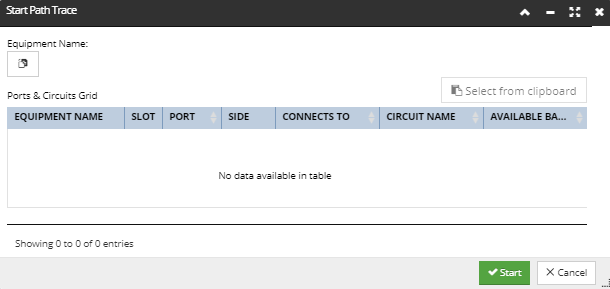
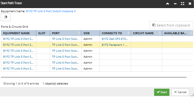
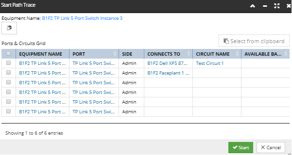
Clicking on the Start Path Trace... button opens the Start Path Trace dialog, which is initially empty, displaying only the Paste from Clipboard button (Equipment Name) and the empty Ports & Circuits Grid, as displayed below:
Clicking on the Paste from Clipboard button (Equipment Name) causes the grid to be populated with the list of Ports from the pasted equipment:
This displays the Equipment Name as a hyperlink for quick access to its Properties dialog, as well as the Ports & Circuits Grid, which lists all Ports for the selected (pasted) Equipment. In addition to Equipment Name, the grid also lists
-
all Ports associated with the selected Equipment, both on the Equipment object itself and on any cards/modules in the Equipment's Slots -
the Slot that holds the card/module each Port is on, if any -
the Side (Admin or Term) that the Port is on -
Equipment on the other side of the Cable that Connects To this Equipment's Port -
the existing (bearer) Circuit a Port is assigned to, if any, and its Available Bandwidth
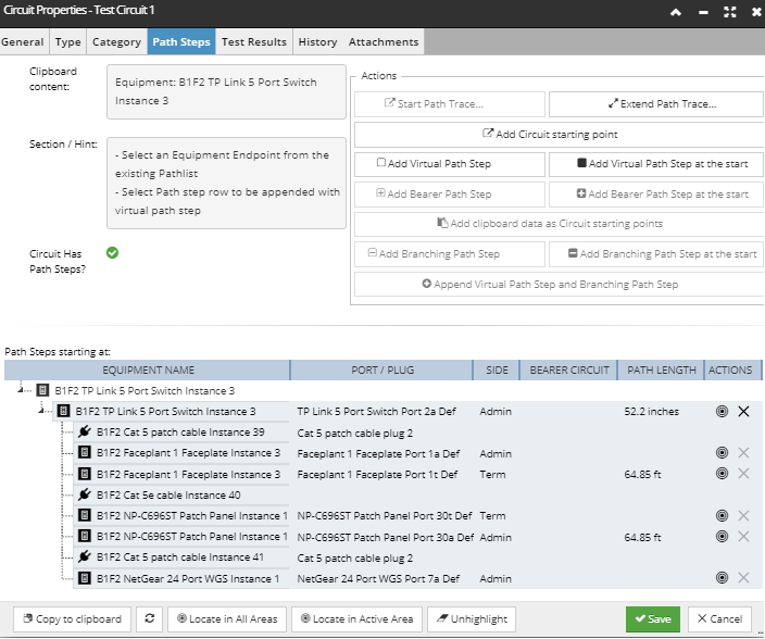
Selecting one of the rows tells IRM which Port the Path Trace should be started from and also enables the Start button at the bottom of the sub-dialog. Clicking that button executes the Path Trace, closes the sub-dialog and brings focus back to the Circuit Properties - Path Trace dialog, which displays an updated Path Steps grid with the results of the trace:
The Path Steps grid displays the following information:
-
Object Name, since the Path Step can be one of the following types of objects: Equipment, Cables, Areas, Pathways, Racks, Locations and other Circuits -
Slot Name, when the Port is on a child card or module
-
Port Definition Name or Plug Definition Name, depending on whether the row entry is Equipment or Cable.
-
the Side of the connected Equipment Port -
name of any existing Bearer Circuits specified for any of the objects included in this Circuit's Path Trace -
the Path Length of the traced Path Step
In addition, the Actions column contains two buttons - Locate and Remove. Note that the Remove button removes the currently selected row entry, as well as any associated path steps if a physical trace is selected. The button is disabled for Path Steps that are a part of a Physical Path Trace sequence, as such a sequence is either all included or not included at all. That is, the Circuit cannot contain only a part of a Physical Path Trace.
In case a Bearer Circuit is assigned to the selected Port, a single row would be populated in the resulting Path Steps grid, but since this is not the case in this example, the Path Steps grid is populated with the selected Port, as well as all other objects connected to it via Cables and internal equipment links.
Note how the complete connection Path from the selected Switch Equipment is traced:
-
starting from the selected Port 2a on the starting Switch Equipment, -
which has a Cat 5 patch Cable connected by its Plug 2 -
followed by another Equipment, a Faceplate, connected to its Port 1a -
Port 1a on the Admin side of the faceplate is linked to Port 1t on the Term side
-
a plant cable runs from Port 1t on the faceplate to Port 30t on a patch panel -
Port 30t on the patch panel is linked to Port 30a
-
a patch Cable connects Port 30a to Port 7a on a workgroup switch
|
 Extend Path TraceThis operation extends an existing Path Step sequence beyond an active Equipment -- recall that an active Equipment stops a Path Trace, so this is how to tell IRM that the Circuit continues from some other Port on that Equipment object.
Conditions for enabling the button:
-
the clipboard contains a single physical Path Step Sequence copied from Path Trace dialog -
a row in a Path Step sequence that ends in an active Equipment is selected
Result:
-
the selected Path Step sequence is extended with additional Path Steps from Path Trace starting at the parent Equipment, same Equipment, or peer Equipment Port(s) selected in the Extend Path Trace sub-dialog. -
the Select from Clipboard button from the sub-dialog is enabled and if clicked causes the appropriate row in the sub-dialog to be selected
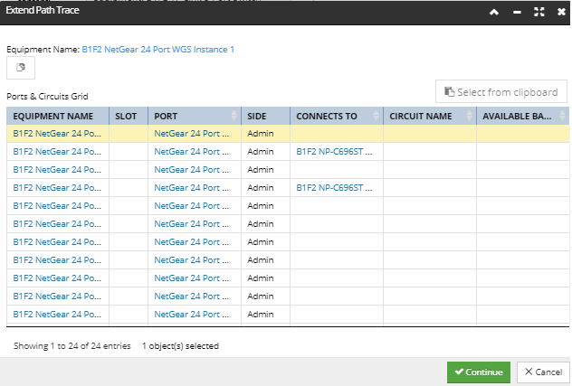
Clicking on this button opens the Extend Path Trace dialog, displayed in the screenshot image below:
which displays the Ports & Circuits Grid for the last active Equipment from the selected Path Trace sequence, which in this example is a NetGear switch. Note that this dialog is almost the same as the Start Path Trace dialog, with the exception that the Paste from Clipboard (Equipment Name) button is disabled, because the Equipment involved has already been selected in the parent dialog.
Some restrictions apply to what is displayed in the Ports & Circuits Grid:
-
In case some of the Ports listed in this sub-dialog are already assigned to another Circuit object, they would appear greyed out, or disabled for selection. -
In case a Port is already assigned to another Circuit object and is channeled, the Available Bandwidth column would display the number of empty channels, and if not, the column displays the value of available bandwidth.
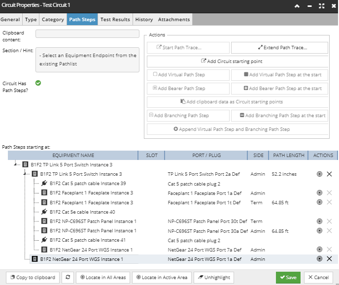
Once an appropriate row is selected, the Continue button is enabled, and clicking on it closes this sub-dialog and brings focus back to the Path Trace tab in the Circuit Properties dialog, listing the added Path Steps in the main Path Steps Grid:
If the selected Port in the Extend Path Trace dialog already has another Circuit assigned and that Circuit is specified as a Bearer Circuit, then only a Bearer Path Step gets added to the Circuit. A bearer Circuit is a kind of "parent" or "super" Circuit that this Circuit can borrow Path Steps and bandwidth (in the form of channels) from. When a Circuit uses a Bearer Path Step, that single Path Step represents all of the Path Steps in the bearer Circuit; the bearer's path Steps are not copied into the referencing Circuit. Likewise, the list of Path Steps shown in the UI does not include an expansion of the bearer's path Steps.
To view the bearer circuit path steps, click on the bearer Circuit's name, which will open a new Circuit Properties dialog on the bearer Circuit and activate its Path Steps tab. If a Port has a Circuit assigned and it's channelized, the Available Bandwidth column should display the number of empty channels, and if it's not channelized it should display the value of the available bandwidth.
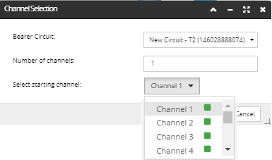
The Channel Selection popup dialog enables selecting a certain number of channels from the selected bearer Circuit to assign to the selected Path Step
It displays the following fields - a numeric stepper and a drop-down menu:
-
the Bearer Circuit drop-down menu that enables Bearer Circuit selection; useful in cases of Port assignment to multiple Bearer Circuits -
the Number of channels stepper sets the number of channels to ''inherit'' from the bearer' circuit. -
the Select starting channel drop-down menu opens a list of all channels of the selected bearer circuit. Selecting one of them specifies the starting channel to ''inherit'' from the bearer circuit. The channel's allocation state is indicated with a colored box next to the channel's name. Possible channel states: -
red box + grayed out - channel is already allocated and is not selectable
-
green box - channel is not allocated and is selectable
-
green box + grayed out - channel is not allocated, but is grayed out (not a valid choice for a starting point) because of an insufficient number of available channels based upon the select starting channel
Once a starting channel is selected, the OK button on the bottom is enabled. Clicking on the button closes the Start Path Trace sub-dialog and brings focus back to the main Circuit Properties dialog. The Path Steps grid is populated with a single row entry that represent the Path Trace sequence from the selected starting point that has a Bearer Circuit assigned.
|
 Add Circuit starting point
This operation adds one or more starting points to the Circuit. These starting points are depicted as the top-level nodes in the Path Steps tree.
Conditions for enabling the button:
-
an Equipment object in the clipboard -
Result:
-
Opens the Start Path Trace sub-dialog, as under Point 1, that lists all available Ports in the Circuit's starting Equipment "family" (the Equipment and it's cards/modules) that are not already used. The only difference between this dialog and the one in Point 1 is that in this case is that it allows multiple selection, which means adding multiple Path Step sequences to the Circuit:
In case the selected Port is connected to something, a path trace is automatically performed and a physical Path Step sequence is added under the starting point node.
|
 Add Virtual Path Step
This operation adds a Virtual Path Step to a Path Step sequence.
Conditions for enabling the button:
-
the clipboard contains a single Equipment, Cable, Space, Location, Area, or non-bearer Circuit -
a Path Step row to be appended with the virtual Path Step must be selected
Result:
-
a Virtual Path Step is added after the selected row -
in case a row in middle of a physical path is selected, the Virtual Path Step is added at end of that Path Step sequence
Note: The second rule also applies to path step removal. As seen in the screenshot image below, Path Steps which are part of a physical path trace sequence can't be removed. In order to remove them, the entire physical path trace sequence must be deleted.
Another Circuit object can be added as a Virtual Path Step, but this only works for Circuits that don't start with a physical Path Step, that is, the Circuit needs to start with a virtual Path Step, or have no Path Steps. Clicking on the Add Virtual Path Step button adds the object from the clipboard to the Circuit under the selected row entry.
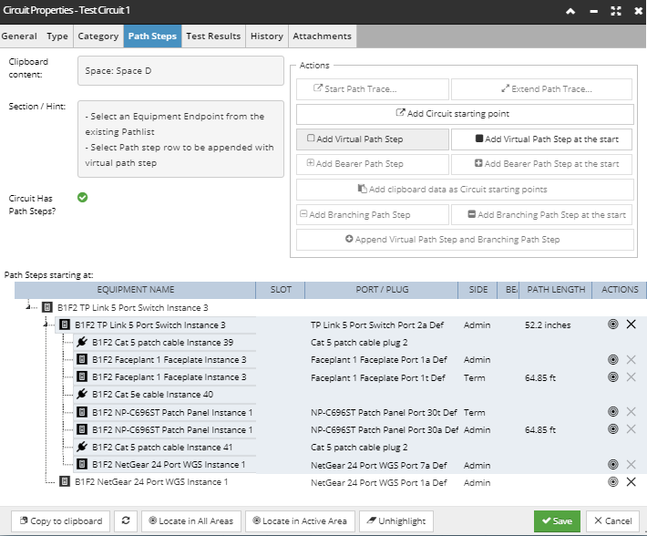
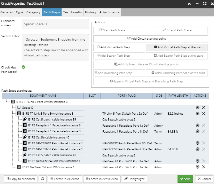
In this example, a Space object is selected in the clipboard and the last (continuation) path step of the first path step sequence is selected
which enables the Add Virtual Path Step button. Clicking on it adds the Space object at the specified position in the Path Steps sequence; it's selected in the screenshot image below:
|
 Add Virtual Path Step at the start
This operation adds a Virtual Path Step to the beginning of a Path Step sequence.
Conditions for enabling the button:
-
the Clipboard contains a single Equipment, Cable, Space, Location, Area, or non-bearer Circuit. -
a Path Step row is selected
Result:
-
a Virtual Path Step is added at the start of the selected Path Step Sequence
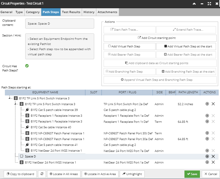
This feature works the same as the Add Virtual Path Step button, described under the previous point, except that the Virtual Path Step is added at the beginning of the selected Path Step sequence. If this button was clicked instead of the Add Virtual Path Step button, for the same use case as described in the previous point, the outcome Path Steps grid would be populated as displayed in the screenshot image below, with Space D now being the initial Path Step:
|
 Add Bearer Path Step
This operation adds a Bearer Path Step to a Path Step sequence. The procedure for the operation is very similar to adding a Virtual Path Step as described in Point 4 above.
Conditions for enabling the button:
-
the clipboard contains a single bearer Circuit that has no Path Steps, or starts with a Virtual Path Step and ends with a Virtual Path Step. To make them more applicable and easier to use, bearer Circuits should normally be created with Virtual Path Steps at the beginning and end. -
the last row in any Path Step sequence to be appended with the Bearer Circuit is selected
Result:
-
a Bearer Path Step is added after the selected row
A Bearer Circuit is a kind of "parent" or "super" Circuit that this Circuit can borrow Path Steps and bandwidth in the form of channels from. If a Circuit uses a Bearer Path Step, that single Path Step represents all of the Path Steps in the bearer Circuit; the bearer's path Steps are not copied into the referencing Circuit. Likewise, the list of Path Steps shown in the dialog does not include an expansion of the bearer's Path Steps, but the list can be seen easily enough by clicking on the bearer Circuit's name, which will open a new Circuit Properties dialog for the bearer Circuit and activate it's Path Steps tab.
The Bearer Circuit Channels Used is the list of the bearer Circuit's channels that this Circuit uses. Bearer circuit channels are assigned by selecting the first channel in the sub-dialog. The application automatically assigns the next available n channels from the bearer circuit such that the sum of the channel bandwidths is equal or larger than the bandwidth required for this Circuit, as specified in this Circuit's Circuit Type.
For example, if the bearer circuit has 10 200kbps channels with channels 5 and 6 already allocated, and a circuit with 1 mbps bandwidth required to channel 3 is assigned, then the result will be bearer Circuit Channels Used = 3, 4, 7, 8, 9.
|
 Add Bearer Path Step at the start
This operation adds a Bearer Path Step to the beginning of a Path Step sequence. The procedure for the operation is very similar to adding a Virtual Path Step as described in Point 5 above.
Conditions for enabling the button:
-
the clipboard should contain a single bearer Circuit that has no Path Steps, or starts with a Virtual Path Step and ends with a Virtual Path Step. To make them more applicable and easier to use, bearer Circuits should normally be created with Virtual Path Steps at the beginning and end.
Result:
-
a Bearer Path Step is added at the start of the selected Path Step sequence
This feature works the same as the one described under Point 6, except that the Bearer Path Step is added at the beginning of the selected Path Step sequence.
|
 Add clipboard data as Circuit starting pointsConditions for enabling the button:
-
-
the clipboard contains one or more physical Path Step Sequences copied from Path Trace dialog
Result:
-
each Path Step sequence in the clipboard becomes a starting point for this Circuit
Note: The Path Trace dialog can be opened for an Equipment object by clicking on the Path Trace button on the bottom of the Ports and Connections tab in the Equipment Properties dialog. This button is enabled if an existing Port is selected and clicking on it opens the Path Trace dialog, which is explained in more detail in the following sub-topic - Path Tracing.
|
 Add Branching Path Step
This operation adds a Branching Path Step to a Path Step sequence.
Conditions for enabling the button:
-
the clipboard contains two or more physical Path Step Sequences copied from Path Trace dialog. -
-
the last row in a Path Step sequence that ends in a Virtual Path Step is selected
Result:
-
a Branching Path Step is added
A Branching Path Step can only be followed by a Virtual Path Step or the end of the Circuit.
|
 Add Branching Path Step at the start
This operation adds a Branching Path Step to the beginning of a Path Step sequence.
Conditions for enabling the button:
-
the clipboard should contain two or more physical Path Step sequences copied from Path Trace dialog
Result:
-
a Branching Path Step is added at the start of the selected Path Step Sequence
|
 Append Virtual Path Step and Branching Path Step
This operation is a convenient way to append a Branching Path Step to a Path Step sequence that could not otherwise be added to in a single operation; an extra Virtual Path Step is first added and then the Branching Path Step is added.
Conditions for enabling the button:
-
the clipboard contains two or more physical Path Step sequences copied from Path Trace dialog -
the last row in a Path Step sequence that ends in a non-virtual Path Step (i.e. an Equipment Path Step) is selected
Result:
-
a Virtual Path Step is appended and then the Branching Path Step is appended, after the selected row
|
|