In IRM Circuit objects are used to define end-to-end service paths across the network infrastructure. By implementing Circuit Management, IRM allows an organization to quickly identify active ports, used media and bandwidth, as well as visualize the route.
IRM supports two type of Circuit objects:
physical (i.e., physical path) - used to identify paths through specific equipment, ports and media
virtual (i.e., logical path) - generally used to define and manage WAN circuits, or virtual circuits where there is some knowledge of the path but not exact detailed knowledge. It is important to note that a virtual Circuit can still include physical elements (physical path steps as described below), and therefore it can actually be a hybrid virtual/physical construction.
The Circuit Properties dialog is the central place in the application for managing Circuit instances, similar to the editors for other Typed Object instances (e.g., Equipment, Cables). In addition to the common tabs (i.e., General, Type, Attachments), the dialog contains the following "special" tabs - the Path Steps tab, the basics of which are covered in this and the Routing Circuits topic and the Test Results tab, which is covered in an earlier subtopic related to general Cable management (click on the link to open that topic).
Since the main purpose of Circuits is defining Path Steps as sequences of different Equipment, Cable and Circuit objects, this topic will serve as an introduction into main parts of the Path Steps tab and put them in context of using Circuit objects in IRM. Another Circuit-related feature in the application is Path Tracing, which enables tracing physically connected sequences of Equipment and Cables, which is another way of creating Circuits. Click on the links for more information about the features.
The Path Steps tab is used to manage the configured connectivity path for the selected ports. A Path Step represents a single point-to-point link in a Circuit. Like a Circuit itself, a Path Step can either be physical, where it indicates a specific Port (or even specific connection points in a Port), or virtual, where it indicates a device, Cable, Location, Space, or Area that the Circuit goes through without consideration of the exact details.
IRM supports the following types of Path Steps:
Physical Path Steps, which are part of Path Trace
Virtual Path Steps, which indicate an Equipment object, Cable, Location, Space, or Area that the Circuit goes through without consideration of the exact details
Bearer Path Steps, which represent another Circuit that this Circuit borrows bandwidth from
Branching Path Steps, which reference more than one Port and allow the Circuit to continue over those Ports. The IRM Circuit model is geared towards linear Circuits, but a Branching Path Step allows the user to model a Circuit that branches over a limited part of its path, usually for purposes of diversity.
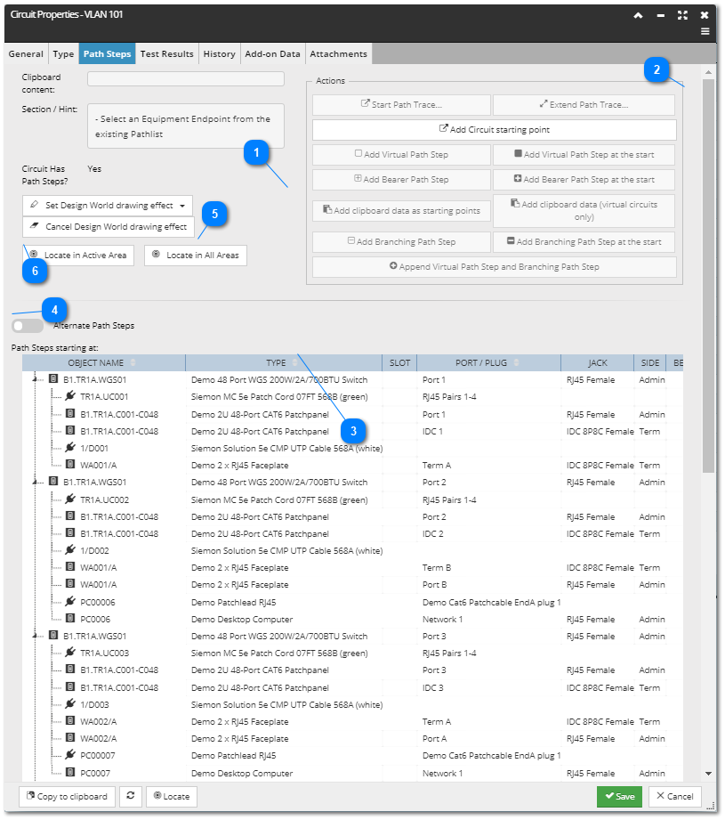
The following screenshot image is an example of a Path Steps tab, while the text below explains its main features:
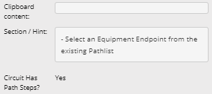
Current selection and hint
This section displays:
names of object currently in the Clipboard
current selection
a Hint message on what actions are enabled based on the current selection, Clipboard content and current Path Step configuration
label indicating if the Circuit contains any existing Path Steps
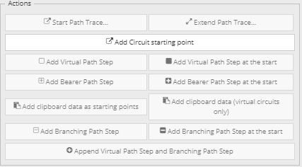
This set of action buttons is related to the section explained in the previous point, that is, depending on the selection, Clipboard content and the current configuration of the Path Steps, these buttons are disabled or enabled. The following topic explain these conditions and what each button does in detail, so click on the link for more information.
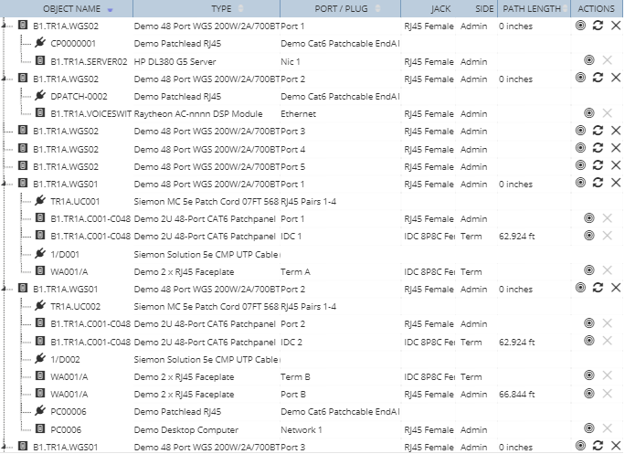
The grid lists all Path Steps defined for the selected Circuit, as well as their basic properties, such as
the corresponding object Type name,
he name of the corresponding Slot and Port (or Plug, depending on the type of the object),
Jack Name and if the Path Step is on the Admin or Term side of the device
if it's a Bearer Circuit and finally,
the Path Length column, which shows the aggregated value of the length of that Path sequence.
The action buttons are similar to the ones that can be found in other places in the application:
- Locate action button highlights the selected Path Step in the Design World.
- Refresh Path Trace button
- the Remove Path Trace action button removes the associated row entry and all row entries below. This action button is disabled for Path Steps that are a part of a sequence of Physical Path Trace, because only the entire physical trace can be removed, not just a part of it.
Additionally, the Path Steps data grid enables the user to control the order of Circuit starting points through the ability to sort the data by the following columns:
Object Name
Type
Port/Plug
Path Length
Notice in the screenshot image above, the data grid is sorted in ascending order by the first, Object Name column. However, having the starting points listed in a controlled order is desirable in some cases, which is why the user can also sort the starting points by the following columns:
Equipment Name (please rename this column to Object Name)
Type
Port/Plug
Path Length
The tree structure and the icons under the first column are explained more in one of the next topics - Routing Circuits.
Above the Path Steps grid there is a toggle/switch button that changes the content of the grid between the Primary Path Steps and Alternate Path Steps. Below is the control in Primary mode:
with the option of changing it to Alternate Path Steps by click on it, which is also indicated by the ON label on the switch icon:
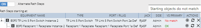
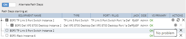
Alternate mode is very similar to Primary mode, except that the Alternate mode shows an additional column added to the Path Steps table - vs Primary. Each row in this column can have one of the following values:
no match – drawn in red, with tooltip "starting objects don't match" (if first object). The first Path Step of the primary mode must use the same object as the first Path Step of the alternate, whether the Path Step is physical or virtual.
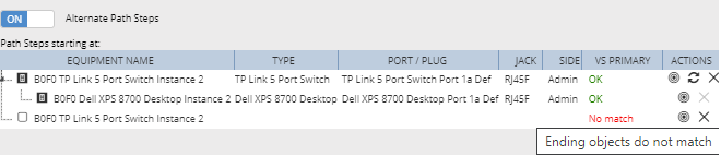
no match – drawn in red, with tooltip "ending objects don't match" (if last object). Similarly as for the previous value, the last Path Step of the primary must use the same object as the last Path Step of the alternate.
not diverse – drawn in red, with tooltip "path steps are not diverse". If a Virtual Path Step or Basic Path Step in the alternate Path Step sequence is not the same as any Path Step in the primary, the "not diverse" error is shown for the alternate, except when the first or last Path Step is virtual. For the Path Steps to be considered the same, all of the fields must be the same.
common bearer – drawn in yellow/orange, with tooltip "path steps may not be diverse". If a Bearer Path Step in the alternate Path Step sequence has the same value for bearer Circuit as any Bearer Path Step in the primary, the "common bearer" error is shown for the alternate.
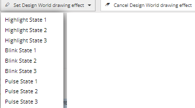
The first button in this group opens a drop-down menu listing different Highlight, Blinking and Pulse effects that can be applied to the selected Circuit object and its assigned objects. Each of these effects have different degrees of intensity, with the suffix "State 1" indicating the lowest and "State 3" highest intensity of the effect.
The second button cancels any drawing effects already applied to the Circuit object.
Locate in Active Area centers the currently opened Area on the path step objects and highlights/ blinks them, so that they are easily seen.
Locate in All Areas opens all Areas where the objects are found in the Design World and each Area centers on the path step objects and highlights/ blinks them, so that they are easily seen.