Elevation Dialog - Other controls
The Elevation dialog consists of several additional data grids and configuration features, as explained in more detail by the following text and screenshot images:
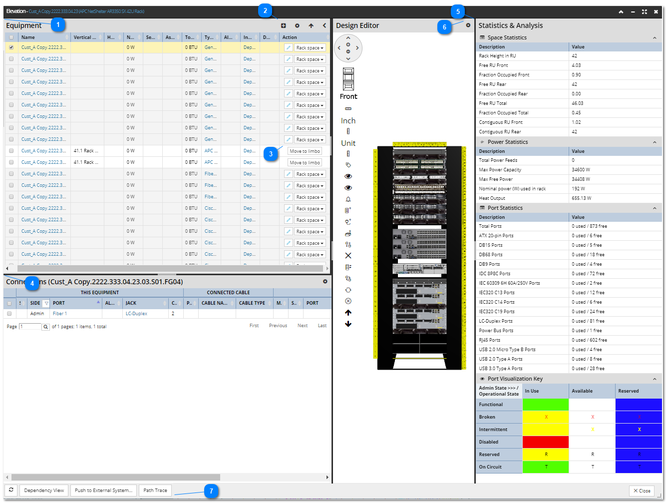
 Equipment gridThis panel contains a data grid that lists all Equipment objects contained in the opened Rack instance, including their basic properties. All objects that are accessible through the "<object> Properties" dialog are displayed as hyperlinks (e.g., Equipment and Equipment Type Properties). As expected, clicking on any of them opens the appropriate properties dialog. The set of columns displayed in this grid is customizable, as explained below.
Selecting Equipment in the Design Editor highlights the corresponding equipment object in the Equipment grid and vice versa.
|
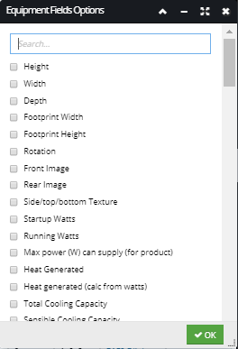
 Additional controls for Equipment grid - Click on the Add equipment button opens the Place Equipment sub-dialog, which allows adding additional equipment into the Rack. See the following section for more details about the sub-dialog - Inserting Equipment in the Rack).  - Clicking on the Toggle columns button opens the Equipment Field Options sub-dialog, displaying several Equipment property fields that can be viewed for all Equipment from the Rack: Clicking on the checkbox next to the column name automatically inserts or removes the selected column from the Equipment grid. Click on the OK button closes the sub-dialog.
 - Clicking on the Equipment positioning toggle button changes whether the Y position values of the Equipment are bottom-up or top-down (that is, whether RU position 1 is at the top or bottom of the Rack). Specifying this option effects values of other Rack properties, like the "RU #" and "Vertical Location in Rack". Clicking on this button toggles the effective value of a temporary positioning direction value used by the Rack Elevation dialog for display purposes. The value of the Positioning Direction property that persists this value can be changed via the Equipment Properties dialog.
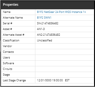
 - Clicking on the left/right arrow toggle button opens/closes the Properties panel and expands/shrinks the Equipment grid panel. The screenshot image below displays a sample Properties panel for a Rack Equipment object. The panel contains a simple data grid that lists basic properties of the selected Equipment object as name / value pairs. Similarly to the Equipment grid, all object types that are accessible through the Properties panel are displayed as hyperlinks (e.g., Equipment, Vendor, Contacts and Circuit Properties). |
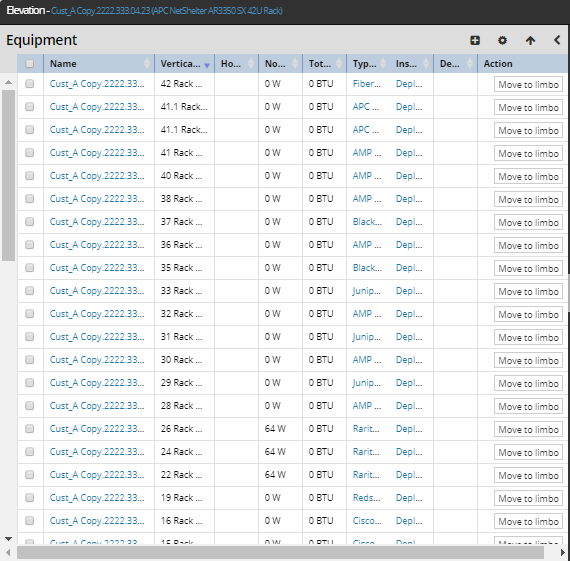
 Limbo controlsAmong other convenient features of Elevation dialog, proper placement of Equipment in a Rack is being determined by checking the value of the property "Rack Position Valid". If the property is set to false, the Equipment is considered to be in the temporary holding area or "limbo", which includes the following characteristics:
-
Rack Elevation will not draw the Equipment -
The Equipment is left out of the calculations determining which space is and isn't occupied in the Rack, for the purpose of placing other Equipment -
The Equipment is still included in all Rack summary / utilization metrics (power, heat, and space). Note that this means a Rack might possibly be more than 100% full, as it can be 100% full with validly placed Equipment and then have some Equipment on top of that that has the property set to false, or simply a large number of Equipment that has the property set to false. -
The row in the Equipment table is drawn with a light grey background for the Equipment that has the property set to false.
The action buttons in the Action column in the Equipment table, at the far right, allow the user to move Equipment in and out of limbo.
The following is the rule under which these can be used:
|
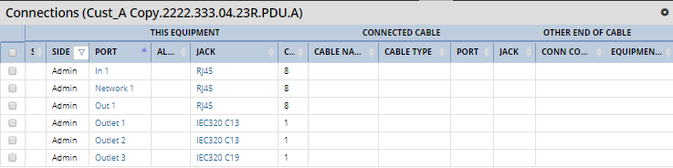
 Connections grid panelDisplays basic Cable Connectivity information for the selected Equipment object, similar to the Ports and Connections tab in the Equipment Properties dialog. Each row in the grid corresponds to one Port in the selected equipment object. The set of columns displayed in this grid is customizable (see points 9 and 10). Similarly to the Equipment grid, all object types that are accessible through the Properties panel are displayed as hyperlinks.
The grid is logically separated into 3 parts:
-
the left part displays Connection properties of the selected Equipment (e.g., Side, Port, Jack, Connection Count) -
the middle part displays Connection properties of the Cable connecting the selected Equipment (e.g., Cable Type, Media Connected) -
the right part displays Connection properties of the Equipment connected to the other side of the Cable (e.g., Side, Port, Jack, Connection Count)
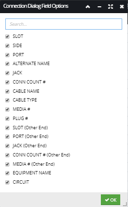
 - This is an additional button available in this panel that enables specifying the fields shown in the grid for all Ports for the selected Equipment from the Rack. Clicking on it opens the Connection Field Options sub-dialog, displayed in the screenshot image below. Clicking on checkbox next to the column name automatically inserts or removes the selected column from the Connections grid. Clicking on OK button closes the dialog. |
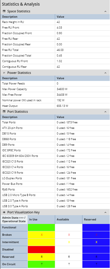
 "Statistics & Analysis" grid panelDisplays various dynamic rack data in accordion groups:
The first three sections display contain space, power and port usage and heat generated statistics data, while the last one shows the visualizations for the various port states. This is covered in detail in the following subtopic - Port visualization.
Please refer to the following topic for more details about the Power management in IRM - Power management. |
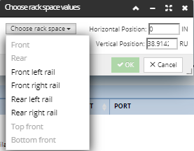
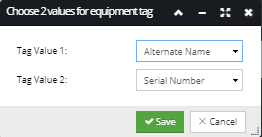
 "Configure Equipment tag" buttonAn additional button in the top right corner of the Design Editor screen enables specifying the values displayed in the Equipment tags / balloons on the left side of the rack in Design Editor. Clicking on it opens the Equipment tag options sub-dialog:
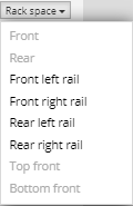
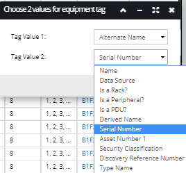
The tags display two values, mutually exclusive (if one is selected as Tag Value 1, it can't be used for Tag Value 2). Clicking on each of the drop-down menus opens a list of available Equipment fields, which values will be displayed inside the tags / balloons for each Equipment in that Rack.
Clicking on the Save button saves the selected Equipment tag values and closes the sub-dialog, while clicking on Cancel button discards the selected Equipment tag values and closes the sub-dialog.
|
 Bottom dialog buttons
-
The refresh button simply refreshes the grid data and the visualizations.
-
The Dependency View button opens the Dependency View dialog for the Rack Equipment.
-
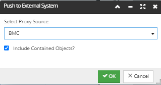
The Push to External System... opens another small dialog for selecting the Proxy Source, which is BMC in the example screenshot below. Also, there's a checkbox for including contained Equipment objects to the BMC Asset Database. This allows the user to push a slotted object, like a chassis and specify that any contained cards/modules/etc. are also pushed.
-
The Path Trace button opens the Path Trace dialog for the Rack Equipment.
|
|