Importing and Connecting plugless cables between Equipment
This use-case will describe how to correctly define the content and structure of the Cable DDR Import sheet to import and connect plug less cables between equipment and the options to select when importing the sheet into the database using the DDR Wizard.
When importing Cable to be routed between Equipment in the same Area the user will need to define the following fields in an CSV import file:
Field Name
Description
Areas
The name of the Area within which the Equipment will be placed eg. Building 1 Floor 1
Type Name
The name of the Cable Type as defined in the Cable Type database e.g.CAT6 Blue
Name
The cable name to help identify the cable being imported. e.g. C0001
Instance Lifecycle Stage
The lifecycle stage to be assigned to the imported cable, e.g. 'Deployed'
End A Equipment Name
This value is the name of an equipment object that already exists in the Area and will be used as the starting point of the cable route. (In future versions this value will allow cables to use Location, Spaces or Text values)
End A Port Number
This is the Port# index value of the port on which the cable will terminate on the Equipment specified in the end A equipment name column. (Port Name is not currently supported)
End B Equipment Name
This value is the name of an equipment object that already exists in the Area and will be used as the ending point of the cable route. (In future versions this value will allow cables to use Location, Spaces or Text values)
End B Port Number
This is the Port# index value of the port on which the cable will terminate on the Equipment specified in the end B equipment name column. (Port Name is not currently supported)
Geometry
for fixed cabling this value is set to Plant for Administrative cabling the value is set to Admin.
Worked Example:
The following is a worked example show how to analyze and prepare the Cable DDR Import sheet to connect CAT6 cable between faceplates and patchpanels.
Preparing the columns data contained in the DDR Import Sheet
We have confirmed that CAT6 Blue is a valid Cable Type using the C&T tree or Cable Type grid. IMPORTANT: the specified cable type must have no Plug Definitions assigned.
Name
The cable name to help identify the cable being imported. e.g. C0001
Instance Lifecycle Stage
The lifecycle stage to be assigned to the imported cable, e.g. 'Deployed'
Areas
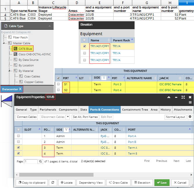
We have confirmed that we are importing the cable into the correct Area named Datacenter
end A equipment name
We have confirmed that the name of the faceplate in the Area is named 101/B
end A port number
We identify and confirm that Port# 3 and Port #4 represent the two rear IDC Ports in the faceplate.
end B equipment name
We have confirmed that a patch panel with the Name TR1A/A01/CPP1 exists in our Rack Elevation.
end B port number
we have confirmed that the cables from the faceplate will terminate on Port# 51 and Port# 52 on the Patch panel in the Rack which relate to IDC Port 3 and IDC Port 4 on the rear of the Patch panel.
geometry
As we are importing fixed cabling we set the geometry column to Plant.
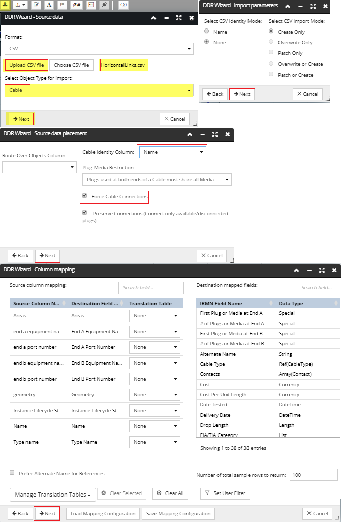
Importing the Cable DDR Import Sheet
After preparing the DDR Import sheet, it is now ready to be imported into the Database using the DDR Wizard as follows:
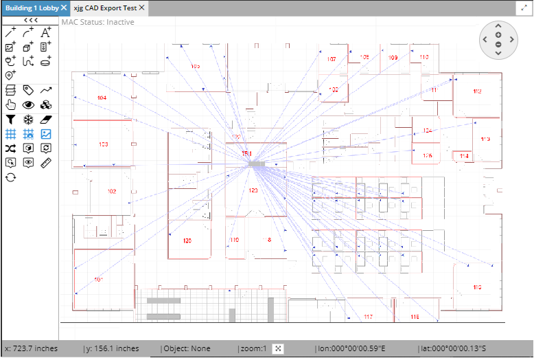
Once the import is complete, the cables will be connected to the Equipment based upon the data contained in the DDR Cable sheet and the cables will be routed point to point within the Area. In our example the final import results looked as a follows:
The user can now either choose to route the cables to represent their actual routes within the building or alternatively, they can just turn the layer off using the Layer Manager interface to hide the un-routed cables.
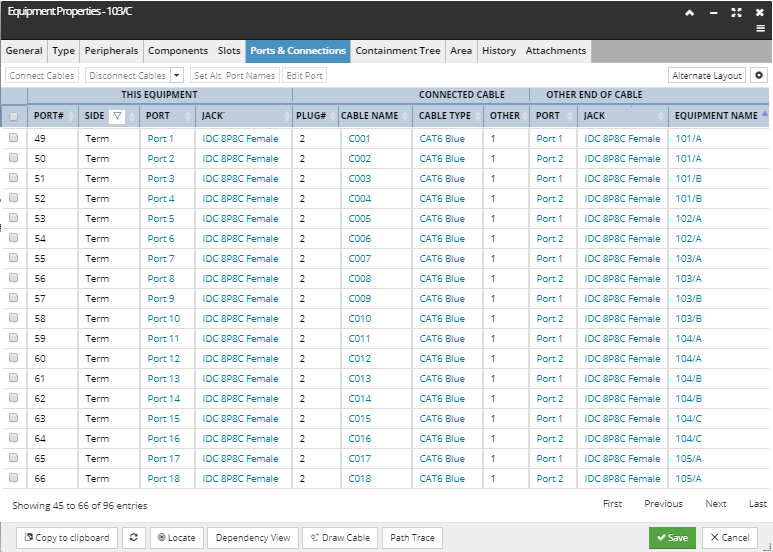
Finally, we can check connectivity on the Patchpanels IDC ports to show how they are now connected to each individual faceplate IDC port: