Visualization of a Tube Box is done via the diagram in the Tube Box View dialog. This diagram visually depicts the connections between the Pathways innerducts that enter from different sides to the Tube Box object.
In the Tube Box View, the inner ducts are represented by fanouts, which represent each pathway inner duct, as can be seen in the screenshot example below:
The Tube Box View dialog also includes the following special-purpose buttons at the bottom of the dialog:
Side Assignment - opens a new dialog that allows the user to select the side of the Tube Box to which a duct should be connected
Duct Mapping - opens the mapping dialog, which allows the user to change the endA/BConnectedPathways.
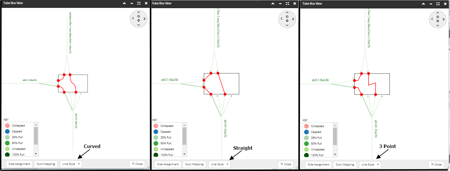
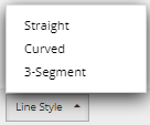
Line Style - a dropdown menu that allows the user to select a style of how the connecting lines are drawn.
Each innerduct is assigned a number assigned - this number is useful for the Tube Box diagram in two ways:
the numbers are shown as labels for each inner duct in the fanout diagram, as can be seen in the screenshot(s)
the numbers are used in the mapping dialog, as explained in the following subtopics.
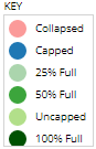
Additionally, the color scheme legend in the bottom-left corner of the dialog provides a high-level indication of the fill status for each inner duct in the diagram.
Additionally, the standard pan & zoom control is also available, and allows the user to conveniently move and scale the diagram.