IRM provides a basic VLAN object which allows users to specify and visualize the devices and port associated to a given VLAN.
NOTE: A VLAN (virtual LAN) is a subnetwork which groups together collections of devices and device ports on separate physical local area networks (LANs).
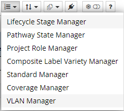
The central place for managing VLANs in IRM is the VLAN Manager dialog, which is accessed from the dropdown list of Extendable Enumerations in the Object Grid toolbar in the main screen:
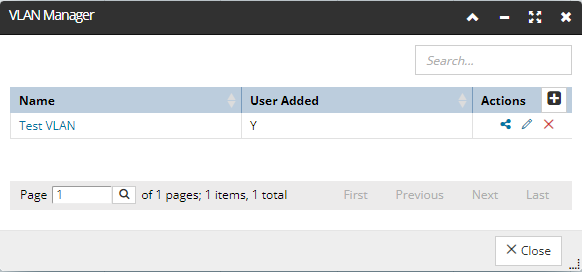
As seen from the screenshot image below, the VLAN Manager is a fairly standard manager-type dialog that has a data grid as its main component. This data grid lists all VLANs by their assigned name, as well as their basic properties, along with additional Action buttons that enable creating, editing, or removing VLANs:
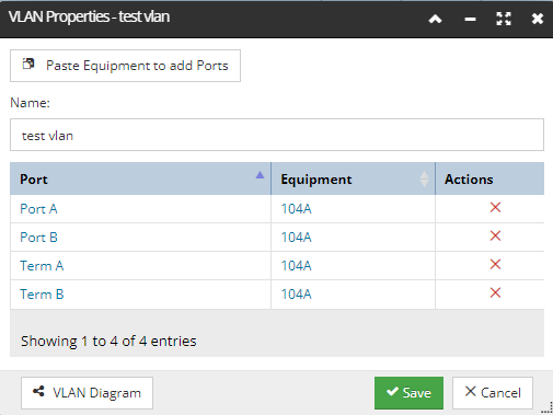
The visualization of a VLAN is accomplished using
using the VLAN Diagram button at the bottom of the VLAN Properties or
using the icon in the Action column for the related VLAN row entry in the VLAN Manager grid.
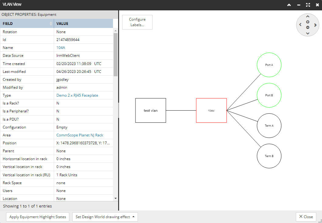
The following is an example of the VLAN diagram for the test VLAN example used in this topic:
The graphical part of the dialog on the right allows the user to visualize what Ports on what Equipment are on a given VLAN. Additionally, the user can select an object in the View, which automatically populates the left side Properties panel, as seen from the example above.
Also, visualization conveniences are enabled, such as
setting the highlight/pulse/blink effects on the objects in the View so they can be visualized in their respective Areas
configuring Labels displayed inside the objects in the View