Planet Associates Inc
×
Menu
Index

Creating Riser Pathways

 
Currently, IRM doesn't have special support for riser pathways, but they can be readily implemented by using stub (short, but non-zero length) Pathways and this topic explains how in the following step-by-step use case scenario. A stub Pathway represents a riser and can be used to track its utilization and loading and depict a reasonably authentic model of how the various Pathways connect across multiple Areas. The use case shows how to create Pathways in two Areas, connect them with a stub that represents a riser, and route a Cable over the resulting Pathway infrastructure.

     Note: if you require accurate riser length, then it is recommended that a sectional elevation drawing of the riser is created in its own area and the Pathway is routed via the sectional area.
1

Create and draw a Pathway to represent a Riser

In the Design World Toolbox, click the Create Pathway button
in order to open the appropriate dialog (with the same name) for creating a new Pathway instance and inserting it into the Design World.
 
Inside the dialog, specify a Duct Pathway Type, Quantity and the Name, i.e. "Duct#" with the starting Index set to 1, which means the first instance would be named "Duct1", the second one would be named "Duct2", etc.
 
By clicking on the Create & Draw Pathway button the Create New Pathway sub-dialog closes and brings focus back to the Design World, with the mouse cursor set in drawing mode. Draw a short Pathway, with a length of about 20 inches:
 
After completing the Pathway, finish it by double-clicking. The resulting Pathway looks something like in the screenshot below:
2

Continue routing the Duct in another Area

 Select the newly created Duct and then select the Continue in Area... option from its right-click context menu;
which brings up a pop-out sub-dialog displaying the list of available Areas in which the Duct routing can be continued.
 
Click on the desired  Area Name to select it and confirm it by clicking on the OK button:
 
Note: If you had a building sectional drawing, it would be selected at this point and the pathway would be shown routed between floors and then the user would Continue In Area to select the destination Floor (as shown below) to show where the pathway enters that floor.
 
Clicking OK closes this sub-dialog and opens the selected Area in the Design World in drawing mode, enabling the user to continue the routing process directly in the new Area.
 
This is finished again by double clicking on the desired point, which in this example is just as a single straight line segment. Now the Pathway is still drawn in the first Area (Building 1 Floor 2) and also drawn in the other Area (Building 1 Floor 3). Notice the round filled circle at the end of the Duct route in the first Area, indicating that the Duct continues elsewhere:
 
The beginning of the Duct route in the second Area has the same circle, indicating that the route has been continued from another Area:
3

Draw a Tray Pathway and connect it to the Duct Pathway

In the Design World Toolbox, click on the Create Pathway button
to again open the appropriate dialog for creating a new Pathway instance and inserting it into the Design World.  This time, specify a Tray Pathway Type, Quantity and the name. 
 
For our example, we're using a simple name - "Tray#", with the starting Index set to 1, which means the first instance would be named "Tray1", the second one would be named "Tray2", etc.
 
By clicking on the Create & Draw Pathway button, the Create New Pathway sub-dialog closes and brings focus back to the Design World, with the mouse cursor set in drawing mode. Draw the specified Tray Pathway in the first Area where the start of the previously drawn Duct route begins, but make sure its final point touches the starting point of the Duct, which brings up a popup menu with a few options:
 
One of the options is Connect to, which brings up the list of available Pathways to connect to, including Duct1 in our example. Selecting the Connect to Duct1 option, the Tray is finally drawn connected to the selected Duct, with another circle at the junction of the Pathways, indicating they are connected:
4

Create and draw a cable through the connected Pathways (through both Areas)

In the Design World Toolbox, click on the Create Cable button
to open the dialog for creating a new Cable instance and inserting it into the Design World.
 
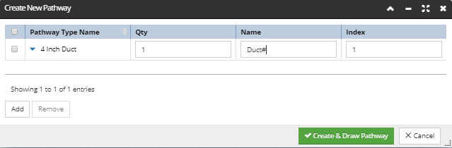
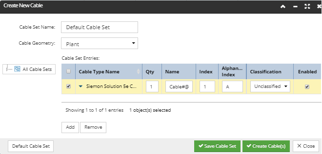
Similarly as for creating a Pathway, specify a Cable Type, Quantity and the Name. As before, we're using a simple name, this time "Cable#@", with the starting Index set to 1 and the Alphanumeric Index set to A, which means the first instance would be named "Cable1A", the second one would be named "Cable2B", etc.
 
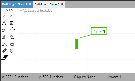
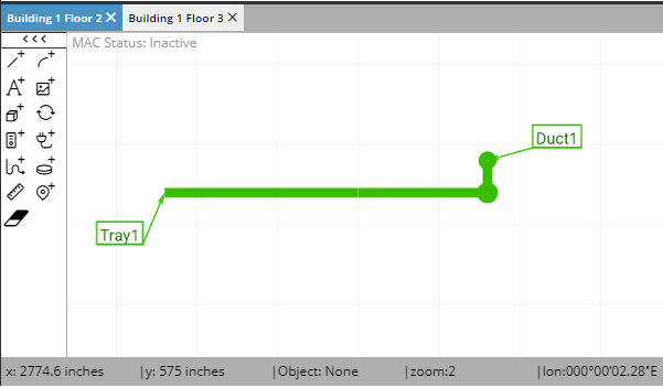
By clicking on the Create Cable(s) button, the Create New Cable dialog closes and brings focus back to the Design World, with the mouse cursor set in drawing mode. Start drawing the specified Cable by selecting the starting point somewhere near the connected Pathways, then select the second point at the beginning of the Tray, which will bring up an extra menu, with the Enter tray option displayed among other options:
 
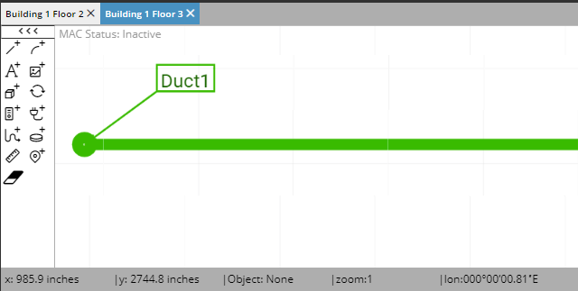
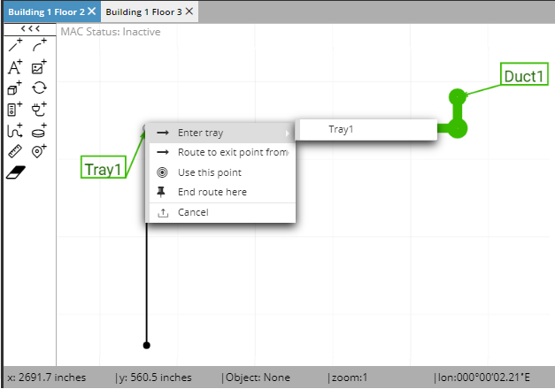
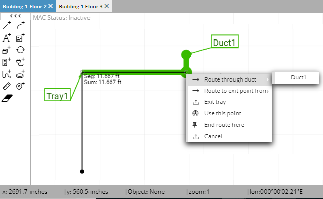
Selecting this option lists the available Tray Pathways which Cable can enter, which is the Tray1 for our example. Select Tray1 and continue routing the Cable through the Tray all the way through it, to the the junction point where it connects to the Duct:
 
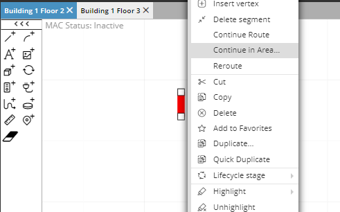
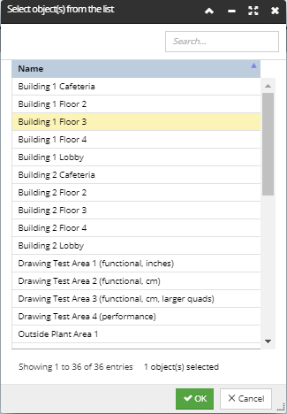
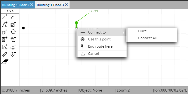
Click on the junction point to open another menu, which displays the Route through Duct option, which is the desired option for this example. Click on that in order to list the available Duct Pathways, which is only Duct 1 in our example:
 
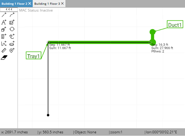
Selecting Duct1 will automatically route the Cable through the Duct route in the first Area, starting where it connects to the Tray, and on to the second Area, where the Duct route continues, and finally to the far end of the Duct.
 
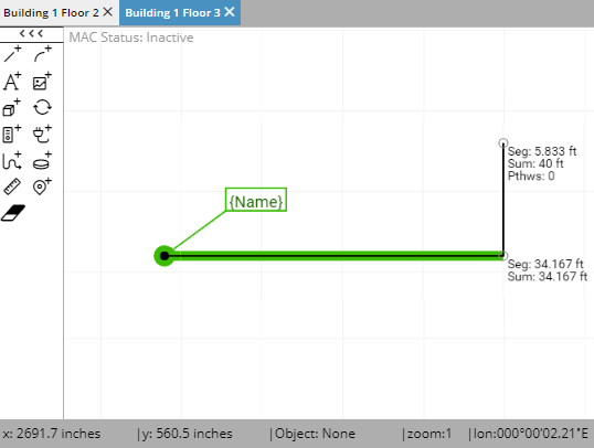
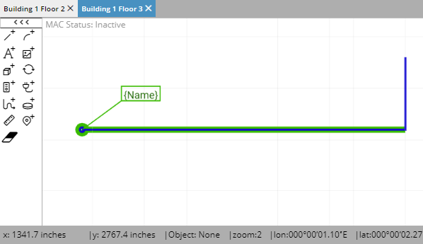
Double click anywhere outside the Duct to finish the Cable routing operation.
 
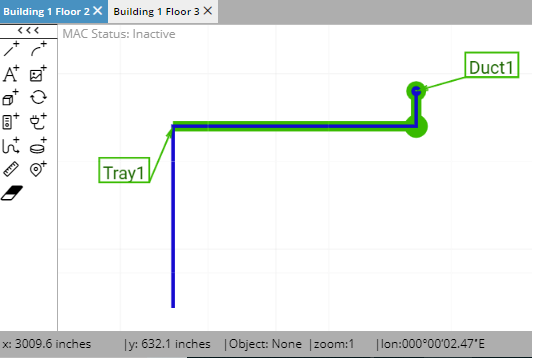
Observe the resulting Cable route through both Areas and through both of the connected Pathways: