Like the Ports & Connections tab in the Equipment Properties dialog, the Plugs & Connections tab in the Cable Properties dialog is used to view and manage connections between Equipment and Cables, but from the perspective of the Cable rather than the Equipment.
In IRM, several objects are involved when connecting Cables to Equipment:
Port - refers to the physical communication and power interface found on an Equipment
Plug - refers to the physical connector type and associated characteristics of a Cable end
Connection Point - refers to the number of physical connection points each Port contains (on Equipment)
Media - refers to the number of strands or pairs or wires found within a Cable sheath
Those objects have some of their characteristics defined by their underlying Type object:
Port Definition - holds Type information for a Port, particular to a specific port on a specific Equipment Type
Jack Definition - holds Type information common to many Port Definitions
Plug Definition - holds Type information for a Plug, particular to a specific plug on a specific Cable Type
Plug Type - holds Type information common to many Plug Definitions
Media Definition - holds Type information for a Media object
More detailed definitions of these objects can be found in the overview sections on Equipment and Cables.
There is a hierarchical relationship between the items above:
Equipment Type
Port Definitions
Jack Definitions
Connector Types
Connection Definitions
Equipment
Ports
Connection Points
Cable Type
Plug Definitions
Plug Types
Media Definitions
Cable
Plugs
Media
The Plugs & Connections tab contains a paginated data grid that displays detailed information about the objects listed above. For Cables with Plugs, there is exactly one row per set of Media that connect to the same Plug (or equivalently, one row per Plug). For Cables without Plugs, there is exactly one row per Media.
Unlike the Ports and Connections tab in the Equipment Properties dialog, this tab displays read-only information and does not allow adding new or breaking existing connections. Therefore, no action buttons are available.
Given that the grid displays information for different types of objects, columns for the same type of object are grouped into the following "super-columns", or group of columns:
Equipment at EndA
This (selected) Cable
Equipment at EndB
Circuit, if assigned,
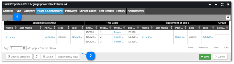
with additional "child" columns listing detailed information about each group. The following screenshot image and text explains the main parts of the Plugs & Connections tab in more detail.
Main grid
The main Plugs and Connections grid displays one row for each Plug in the current Cable object (the one being edited).
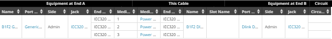
As mentioned earlier, it is divided into four column/properties groups:
Equipment at End A – the fields describing the Equipment side of the connection, including the Port Name and Number, Slot Name (if applicable), Side (Admin or Term), Jack Type and Connection Count
This Cable – the fields describing the Cable side of the connection, including the Media, Plug number, Cable Name and Type, the other end Plug number and the other end Media
Equipment at End B - the fields describing the Equipment at the other end (end B) of the connected Cable; has the same fields as the first group
Circuit – lists any Circuits that the row's Media carry
Standard pagination controls for listing though grid data are displayed under the grid:
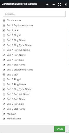
- the "gear" button located above the Plugs & Connections grid opens the Connection Dialog Field Options sub-dialog that enables specifying which columns will be displayed in the grid by clicking on the checkbox next to the name of the field / column, as displayed in the screenshot image below: