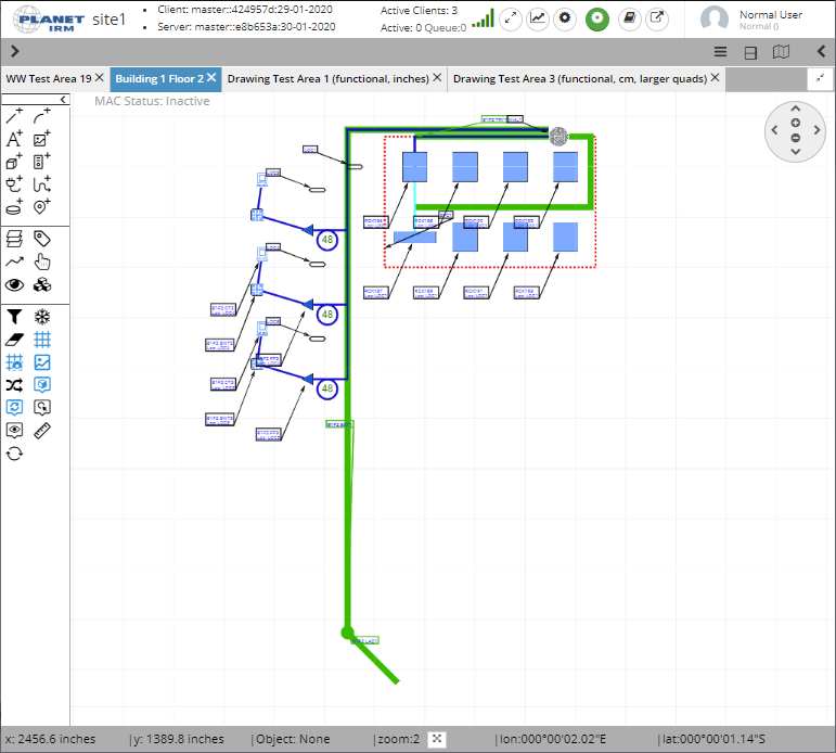
IRM utilizes an HTML canvas to display a Site’s primary drawing information, using a top-down or "footprint" view to represent floor plans, site plans or geo-spatial maps.
Other, more specialized visualizations can be accessed from within the Design World, such as:
Rack / Cabinet / Wallboard Elevation
Maintenance Hole Butterfly View
Dependency View
The Design World contains three main types of objects:
Geometry (either imported from CAD/GIS formats or drawn using IRM drawing tools):
polylines (connected sequence of line segments created as a single object)
arcs
text
block shapes
images
Managed Objects (overlaid on top of the Geometry to represent "As Configured" or "As Proposed" managed infrastructure)
Equipment
Pathways
Cables
Maintenance Holes
Locations
Spaces
Circuits
Auxiliary objects (not directly visible, they are still present and affect Design World rendering):
Areas
Layers
Coordinate Systems
Blocks
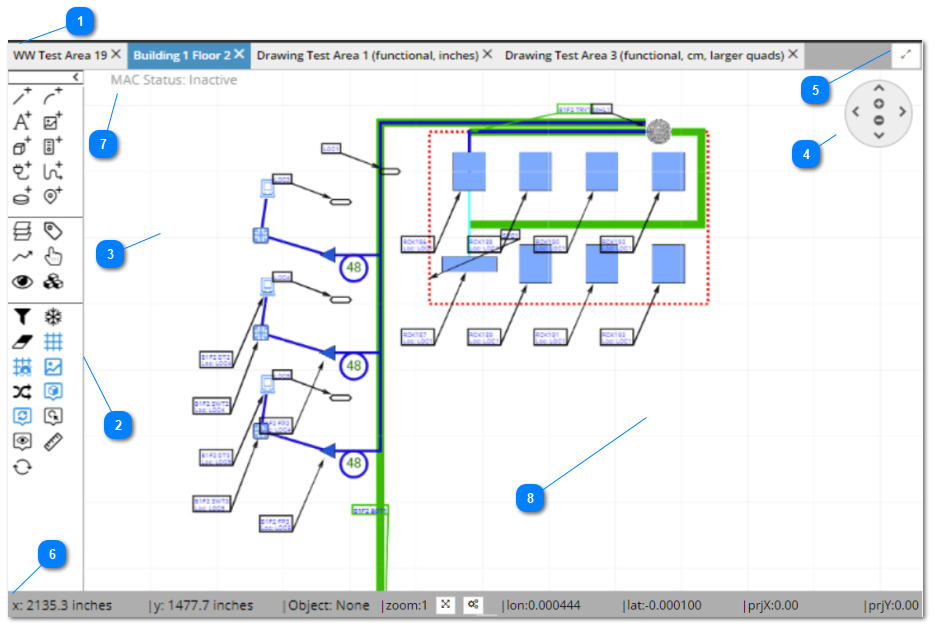
This section focuses on the main UI features of the Design World. The following screenshot(s) and text explain various details about this feature and its related sub-dialogs:
Area tabset bar
This bar serves as a container and manager for multiple opened Area tabs. Each tab represents an Area object that is currently opened in the Design World (Area name is displayed as a text label in the tab itself).
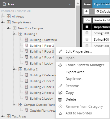
An Area is opened by click on the Open option from the Area's context menu in the C&T Tree.
An opened Area can be closed by click on the x button next to the Area name in the Design World tab. If multiple tabs are open, click on the tab name makes that tab (Area) currently displayed (active, opened).
The Drawing Area (Canvas) is the white rectangular area that displays the actual objects of the opened Area. The following points cover the various sub-parts of this feature in more detail.
This tab displays several read-only labels and has only informational purposes. It displays the type of the object (Super Category) currently under the mouse cursor, the current zoom level, the current x,y position of the mouse cursor and its geo-coordinates (longitude and latitude) if applicable.
- Zoom To Fit Area - click on this button zooms out / in the drawing in a way such that all objects are visible and fit the current dimensions of the drawing canvas. This is convenient if you accidentally pan or zoom to an empty part of the Design World and want to quickly re-locate your objects.
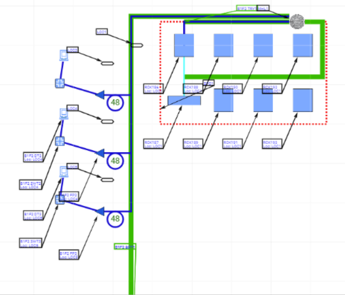
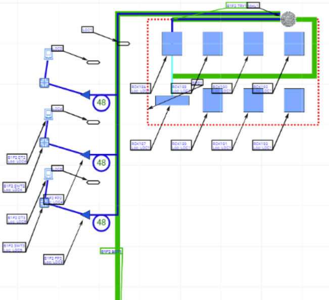
The Preview feature simplifies calculations to ease the burden of viewing large amounts of information in the data center. Essentially it converts detailed objects such as Equipment, Space, Cabels, etc. into simple shapes such as lines and triangles. The goal is to eliminate unnecessary and overlapping features, making it easier to navigate without selecting individual tools or cables.
The feature works in three way toggle button to switch between the 3 modes:
Auto Mode: Automatically activates the Preview Mode when the zoom level is high and the number of objects to be displayed is large. Enabling the Circuits display in the Layer Manager dialog further clarifies the view.
Preview Mode: Active when the zoom level is greater than 1. Simplifies the view by converting complex objects to simple shapes. You cannot select individual tools or cables in this mode. This is especially for easy navigation with wide selection and managing large datasets.
No Preview Mode: Default view where you can see all the data in its detail.
Important note: when Preview mode is On:
Layer rendering options will not have the expected effect.
Business objects like Equipment, Cable, Maintenance Holes, etc. are drawn only as decorations and therefore do not have their usual functionality.
In the top-left corner of the drawing canvas there is a designated area for MAC controls. A text label and 2 additional buttons are used to quickly view MAC status, join an existing MAC, or create a new MAC.
For more details about the MAC feature, click on the following link - MAC operations.
The drawing itself is located on the central drawing / canvas area of the Design World. In this example, a drawing displays a cubicle layout in an office.