Inserting Cable(s) in Design World
After Cable properties have been specified, the user can finish the Cable creation / Cable edit process and start the Cable drawing/routing process in the opened Design World Area. By clicking on the Save Cable Set or the Create Cable(s) button the Create New Cable dialog closes, and the focus is back to the previously opened Design World where the Cable creation was initiated.
NOTE: If an equipment object is selected in the area when trying ot insert a cable, a dialog is displayed asking if the user want to add the cable to just the seleced object or if they want to manually route the cable.
Notice the mouse cursor is automatically in "cross hair", indicating Cable routing mode:
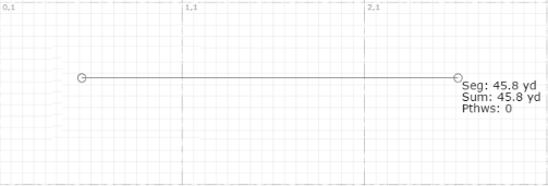
A single left-click on the canvas (drawing area) creates the first point in the Cable route, indicated by a hollow circle icon. The cursor coordinates and length of the Cable route are displayed at the end of each cable segment within the cable route. Cable routing is finished by double-clicking the left mouse button.
Once a cable exists in an Area, it can be selected, which shows all associated routing vertices. From here, additional context menu options are available:
-
Move Existing Vertex: The user can modify an existing vertex point by clicking on the Vertex and moving it to a new position.
-
Delete Existing Vertex: The user can remove a vertex from the route by:
-
Selecting the Cable(s) in the Area
-
Moving the cursor to the Vertex to be removed
-
Then selecting
Delete Vertex from the context menu.
-
Add Vertex - The user can currently only add vertices to the cable route by using the
Re-route context menu option. This allows the user to re-specify the route between the existing defined endpoints of the cable.
View / edit Cable's Design World appearance
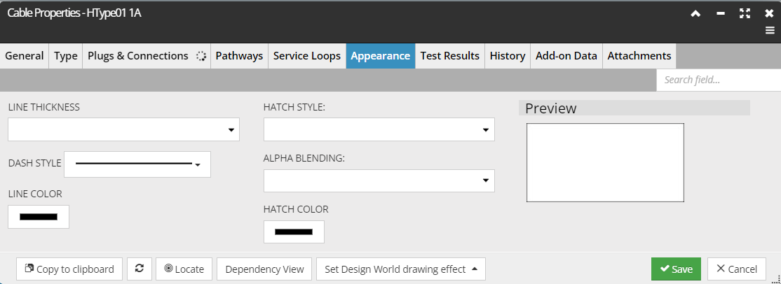
The Appearance tab allows the user to manage the visual representation of the Cable in Design World. This tab is similar to the Drawing tab in the Style Editor subdialog of the Layer Manager and contains a set of Line properties and Hatch properties, along with a Preview section. These properties directly affect the appearance of the Cable lines in the Design World.
Selected Cable appearance
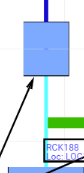
In some cases, it's useful for the user to know which end of a Cable is End A and which end is End B. To identify the Cable ends, a decoration appears (only) when a Cable is selected in the Design World, as seen below:
Notice that small arrows are drawn along the Cable, near each end, pointing from A to B, with End A on the right and End B on the left in this example.
Further details:
-
Arrows point towards the B end, along the direction of the Cable segment on which they’re placed. In the diagram above, the Cable was drawn right-to-left, or “backwards” from how they are usually drawn.
-
Arrows are placed 1 foot away from the ends of the Cable.
-
For a Cable less than 3 feet long, only 1 arrow is placed, at the midpoint of the Cable.
-
For a Cable less than 1 foot long, no arrow is placed to avoid clutter/confusion.
-
As with handles, the size of the arrow does not scale with zoom level.
-
The arrows are only drawn when a Cable is selected in the Design World.