4.3.7.3. Installing Administration cable into selected Equipment within the Design World
The following use case demonstrates how to install and connect a Cable into an Existing Rack or Equipment within the Design World. This is useful for installing different types of Administrative Cables, or jumper connections used to connect between Equipment within the same Rack or between cards contained in the same Equipment.
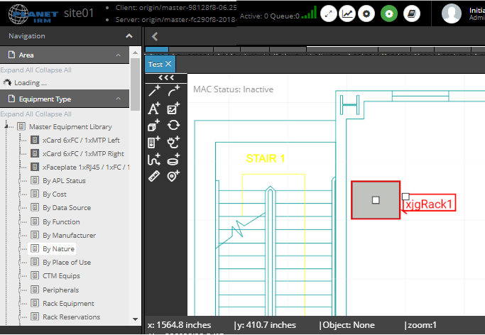
Select Equipment or Rack in the Design World where the cable is to be installed
Select an Equipment or Rack within the design world where the cable will be installed.
TIP: The user can achieve the same result of this step by selecting Draw Cable button from within the Equipment properties Ports & Connections tab
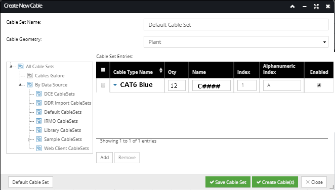
Click the "Create Cable" button from Design World toolbar menu
This starts the Cable insertion process by allowing user to define ad-hoc or pre-defined Cable Sets via the Create New Cable dialog, as explained in the next step.
The first step in inserting a new Cable is to select a Cable Type from the Cable Set Entries pulldown or by selecting a predefined Cable Set in the Cableset Tree. In this use case the CAT6 Blue cable is selected and its assigned named will start a C0001 (the following section explains this cable type creation - Defining new Cable Types).
Check the Enabled checkbox next to the appropriate row entry to enable the Create Cable(s) buttons. Clicking on this button closes the current dialog and will add 12 CAT6 Cat cables into the select Design World Equipment/Rack.
IMPORTANT: There is no option to route a cable if an Equipment Object is already selected when creating new cable entries.
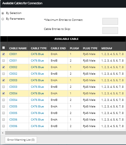
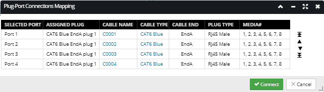
In the above example, the user has select End A for Cables C0001 through C0004.
NOTE: as both ends of the cable are not yet connected both cable Ends are listed identified as either End A or End B.
After clicking the Connect... button, the user has the option to change the order of termination by re-arranging which cable numbers will connect to which port. Generally, the user can accept the defaults and continue by clicking the Connect button.
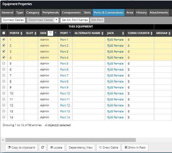
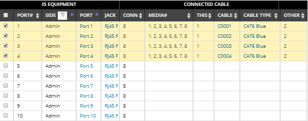
The Connections dialog for the Equipment is updates to reflect the Cable connections:
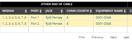
Steps 4 and 5 can now be repeated to connect the other ends of the cable to a different Equipment by opening the properties of the Equipment to which the cables will be connected.
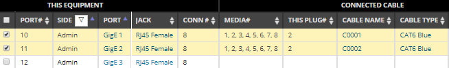
Once the both ends of the Cables are connected , the Ports and Connection dialog will appear as follows:
The above example, shows cables C0001 and C0002 connected to ports GigE 1 and GigE 2 on a server.