4.3.7.2. Insert and Connect Cables from Faceplates to Rack Equipment
The following screenshot images and text explain a use case scenario for inserting a Cable and connecting it from a faceplate to rack equipment. The equipment and cables used for this example are coming from the IRM sample data.
This use case scenario assumes the appropriate equipment is created and inserted in Design World. These preliminaries are covered in previous topics as follows:
Click the "Create Cable" button from Design World toolbar menu
This starts the Cable insertion process by allowing user to define adhoc or pre-defined Cable Sets via the Create New Cable dialog, as explained in the next step.
The first step in inserting a new Cable is to select a Cable Type from the Cable Set Entries pulldown or by selecting a predefined Cable Set in the Cableset Tree. In this use case the CAT6 Blue cable is selected and its assigned named will start a C0001 Cat5 Patch Cable (the following section explains this cable type creation - Defining new Cable Types).
Check the Enabled checkbox next to the appropriate row entry to enable the Create Cable(s) buttons. Clicking on this button closes the current dialog and puts the focus back in the Design World, where the cable instance(s) can be routed. The mouse pointer is changed to a cross, indicating that IRM is in Cable routing mode.
The user should use the left mouse button to specify the cable route from the center of the Faceplate to the center of the Rack. Once the Cable line is drawn from the Faceplate to Rack Equipment, clicking the right mouse button will end the cable routing and create the cable instance in the Design World.
The following steps outline how to connect the cable to the faceplate Equipment and Patchpanel located in the Rack.
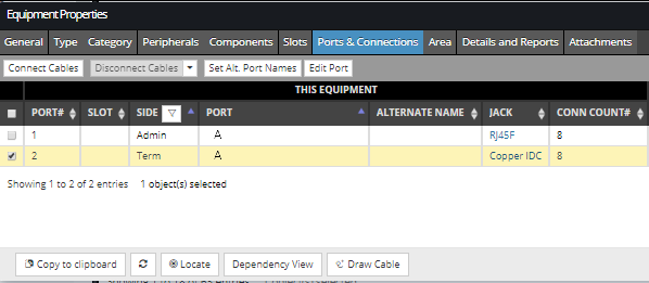
Click on the Ports & Connections tab in the Equipment Properties dialog. This displays all Ports and their Connections for the selected Equipment object. For more details about this tab see the following topic - Ports, Jacks, Plugs, Connection points.
To connect Cable(s) to the selected Equipment, a non-connected port entry needs to be selected, which automatically enables the Connect Cables button on the top of the dialog. Once an appropriate port entry is selected, click on the Connect Cables button. This action opens the Available Cables for Connection sub-dialog, explained in the next step.
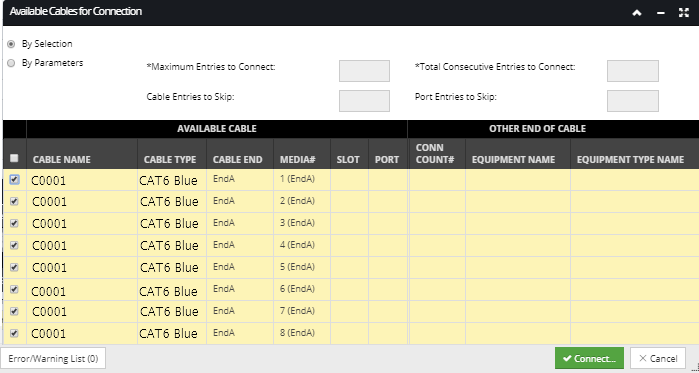
Select the Cable Meida entries to connect to the Faceplate Port
Using By Selection option, allows the user to select the cable media entries in the Available Cable grid to use to connect to the selected Equipment Port(s). After selecting the Cable Media, click the Connect... button to specify how the media will be terminated on tehe Faceplate port. this dialog allows the user to specify different types of wiring connections e.g. 568A or 568B.
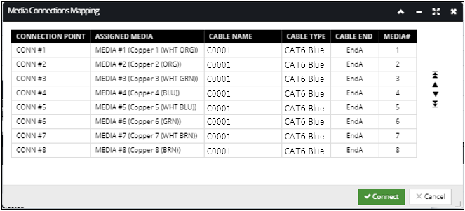
The screenshot image below displays the default Media Connection Mapping that will be specified for this example:
The connection mapping can be rearranged by following these steps:
select the appropriate Media row entry by clicking on the appropriate row under any of the columns, except under the first one, as that one is not selectable and displays only the Connection Point name
click on the up/down arrows on the right of the grid to move the selected Media one row/place up or down
click on the far up/far down arrows on the right of the grid to move the selected Media to the top/bottom row/place
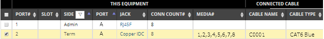
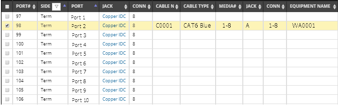
After the Media are mapped appropriately, clicking on the Connect button closes the sub dialog and brings focus back to the Ports & Connections tab in Equipment Properties dialog displaying the full connection, as shown in the next step.
The appropriate fields under the Connected Cable and Other End of Cable column groups are populated (e.g., Cable Name, Cable Type, Media#). Click on the Save button to save the newly created connection.
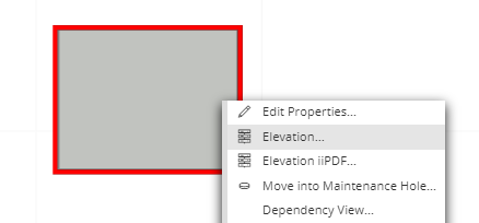
This can be done by selecting the Elevation.. context menu option after selecting the Rack in the Design World or from the Equipment Grid.
TIP: if the user knows the Equipment in the Rack to which the cable will connect, then the user can select the equipment directly from the Equipment grid, without need to go via the Rack Elevation.
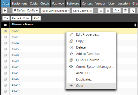
Select the appropriate equipment object, either by selecting it in the Design Editor, or by selecting it in the Equipment Grid. Once it's selected, click on the hyperlink under the Name column in the Equipment grid to open the Equipment Properties dialog for the selected equipment object.
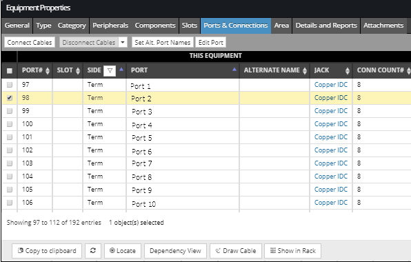
Clicking on the Ports & Connections tab in the Equipment Properties dialog displays all ports and their connections for the selected equipment object. For more details about this tab see the following topic - Ports, Jacks, Plugs, Connection points.
To connect selected equipment to the other end of the previously created and connected Cable, a non-connected Port needs to be selected, which automatically enables the Connect Cables button, which opens the Available Cables for Connection sub-dialog, as displayed in the next step.
Click on the checkbox next to the appropriate cable row entry from the grid in the Available Cables for Connection sub-dialog. This sub-dialog lists all Cables that have an end near the same position in the Design World as the equipment. Selecting the appropriate Cable enables the Connect... button and clicking on it opens an additional sub-dialog - Media Connection Mapping, that enables the user to specify for each Cable Media the exact Connection Point of the selected equipment to which it will connect.
The screenshot image below displays the default Media Connection Mapping that will be specified for this example:
The rearrangement is can be done following these steps:
select the appropriate Media row entry by click on the appropriate row under any of the columns, except under the first one, as that one is not selectable and displays only the Connection Point name
click on the up/down arrows on the right of the grid to move the selected Media one row/place up or down
click on the far up/far down arrows on the right of the grid to move the selected Media to the top/bottom row/place
After the Media is mapped appropriately, clicking on the Connect button closes the sub dialog and brings focus back to the Ports & Connections tab in Equipment Properties dialog displaying the full connection.
The appropriate fields under the Connected Cable and Other End of Cable column groups are populated (Cable Name, Cable Type, Media#). Clicking on the Save button saves the newly created connection.