Cable graphical representationWhen adding a Cable, if either the Equipment or Pathway object associated with either Cable End is not first placed in the Butterfly Layout, the drawing operation is aborted and a warning message is shown - "This Cable cannot be drawn because the Pathway or Equipment associated with one of its ends is not available in the Butterfly Diagram. Please add that object first."
Note: when drawing the Cable Line it is terminated with a double-click. If the double-clicked location is away from the the duct/equipment endpoint then the last line segment will be auto-drawn. If the cable does not end at an equipment or duct then the endpoint will be where the user double-clicked.
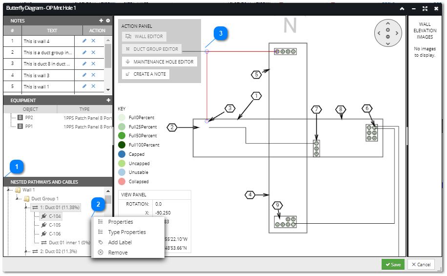
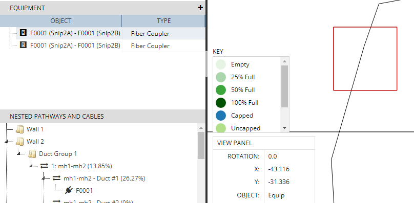
Drawn Cables within the butterfly layout can be later manipulated in a similar way as in the Design World. Once a Cable is selected, its anchor points are also displayed and highlighted (separately, in a different color). Clicking and dragging on the cable's anchor point moves the attached cable segment(s) along with the cursor.
Note: any change to the routing of a cable in this dialog will not affect the real route of the cable object in the Design World.
The following special features are enabled in the Butterfly Layout, to help with drawing Cable Lines:
-
When selecting a Duct, the selection is in the pulse highlight state in the central Butterfly drawing -
When selecting an inner duct, the parent duct in the central butterfly layout is highlighted by pulsing the selection. -
When selecting a Cable, both Cable and Duct endpoints within the butterfly layout are highlighted by using a pulse highlight. -
If the Cable is routed via an innerduct the parent Duct that is placed in the butterfly layout is pulsed.
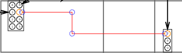
When the user draws the Cable Line in the Butterfly View the correct start and/or end points for the Cable Line are automatically highlighted and selected allowing the user to just specify the route between the 2 endpoints. However, there are three possible scenarios where a cable is not routed between ducts and this will change the routing as specified in the following 3 scenarios:
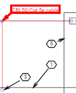
Scenario1: Cable enters the Maintenance hole via a duct but exits as a buried cable
In this case the beginning of the Cable Line is placed at the Pathway's representative circle in a Duct Group and the other end of the cable is paced in the center of the butterfly allowing the user to specify the route the cable takes to the point where it exists the Maintenance Hole:
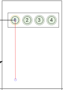
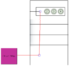
Scenario2: Cable enters the Maintenance hole via a duct and connects to an Equipment within the Maintenance Hole
In this case the beginning of the Cable Line is placed at the Pathway's representative circle in a Duct Group and the other end of the cable is paced in the center of the equipment within the butterfly layout, allowing the user to specify how the cable is routed between the two endpoints by selecting routing points within the butterfly layout.
Scenario3: Cable enters the Maintenance hole via a duct and is not connected or routed any further
In this case the beginning of the Cable Line is placed at the Pathway's representative circle in a Duct Group and the other end of the cable is placed in the center of the butterfly layout, allowing the user to specify how the cable is routed.
| 
 .
.