Managing Equipment in Butterfly Diagram
-
an ability to
assign Equipment into the
Maintenance Hole and specify its
location within the
Butterfly View layout -
an ability to
run and
connect Cables to the
Equipment assigned to the Maintenance Hole
As a general design principle, equipment in a Maintenance Hole is treated very similarly to equipment in a Rack or Cabinet in sense that the Lifecycle Stage of equipment in a Maintenance Hole can be set to Deployed, or to some other Design World compatible stage, but that Equipment is not drawn by the Design World rendering code, only in the Butterfly View.
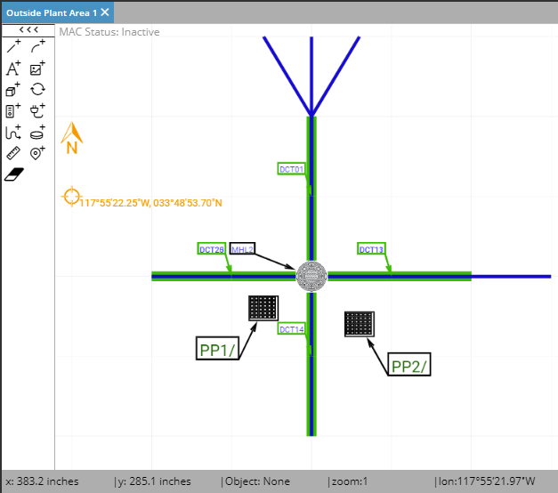
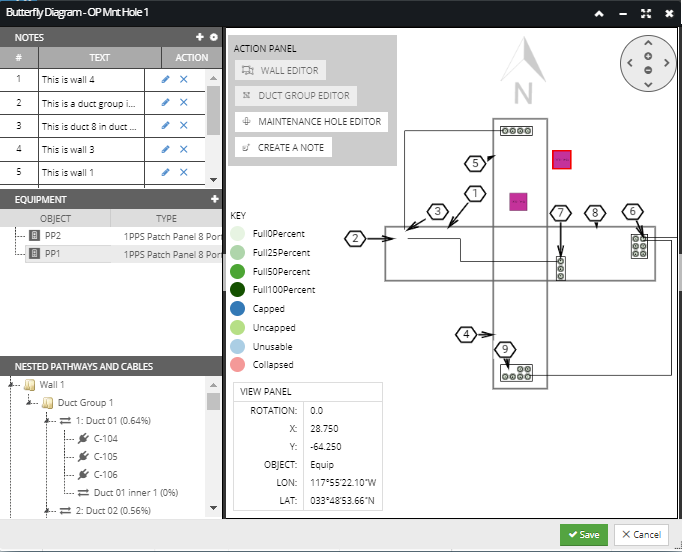
The first step in adding equipment into a Butterfly diagram is to make sure the appropriate equipment is placed near the Maintenance Hole in the Design World. The example in the screenshot image below shows 2 patch panels - PP1 and PP2 placed from each side of the Maintenance Hole (the reason why there are 2 is because we will demonstrate 2 different ways of adding equipment to a Butterfly Diagram).
Placing Equipment into a Maintenance Hole from the Design World
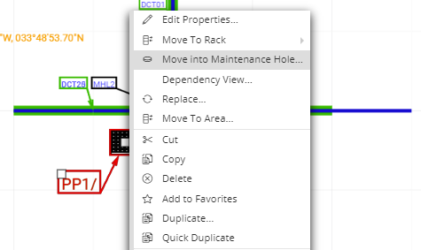
It is possible for equipment in the Design World to be directly added to a Maintenance Hole via the context menu option Move into Maintenance Hole... which is immediately underneath the Move to Rack option. This is convenient in situations when you want multiple equipment instances to be added to the Maintenance Hole in a few simple operations and then later position and manage them appropriately inside the Butterfly Diagram.
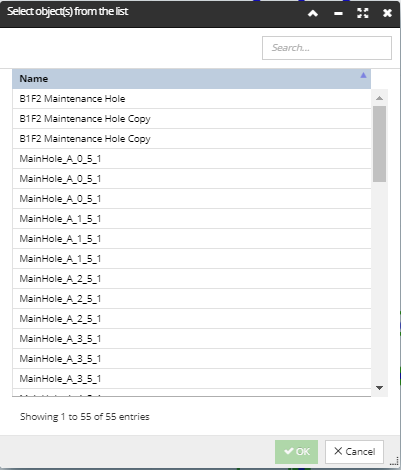
Clicking on this option opens a pop-out dialog that lists all Maintenance Holes:
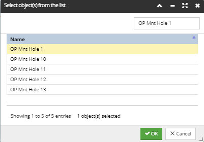
The full list can be filtered using the Quick Search feature at the top-right of the dialog, simply by entering the name (full or partial) of the appropriate Maintenance Hole:
This action is confirmed by clicking on the OK button, which is enabled once something from the list is selected. The sub-dialog then closes and the Equipment is removed from the Design World.
Placing Equipment inside the Maintenance Hole inside the Butterfly Diagram
Once the operation in Design World is finished, detailed positioning of the equipment inside the Butterfly Diagram can be carried out.
This is done in several steps:
-
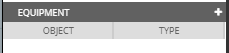
Add Equipment objects into the
Equipment panel by clicking on the
+ action button at the top-right corner of the panel:
-
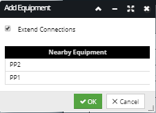
which brings up a small sub-dialog displaying a list of Equipment objects placed nearby the Maintenance Hole in the Design World:
Note that in addition to listing the nearby Equipment objects, the sub-dialog also contains the Extend Connections checkbox that gives the option of extending or breaking any existing Cable connections before adding the Equipment to the Butterfly Diagram. This occurs because the Equipment is moved to a different Design World location (that of the Maintenance Hole), and any Cables that are to remain connected must be run to the new location.
-
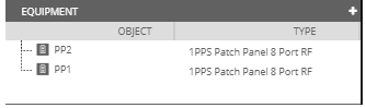
Once both Equipment objects are added, they are visible in the
Equipment panel, as displayed below:
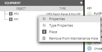
The Equipment panel lists all Equipment added to the Maintenance Hole by name and Type. In addition, this panel enables additional actions available through the context menu:
-
The
Properties and
Type Properties options open the appropriate Equipment Properties and Equipment Type Properties dialogs.
-
Remove from Maintenance Hole removes the Equipment object from the Maintenance Hole; it will still exist in the Design World and will now be visible there.
-
Place enables placing the Equipment inside the Butterfly View layout. After it's been initially positioned, it can be repositioned by drag and drop.
Note that selecting an Equipment object in the Butterfly Diagram also selects it in the Equipment panel; this is similar to how selection of Cable and Pathway objects is handled.