This section will demonstrate in detail how to place the imported drawing into the selected Area, as well as different UI details and caveats within this dialog that allow the user to basically finish the CAD Import operation
Specify the Coordinate System and the Import Mode
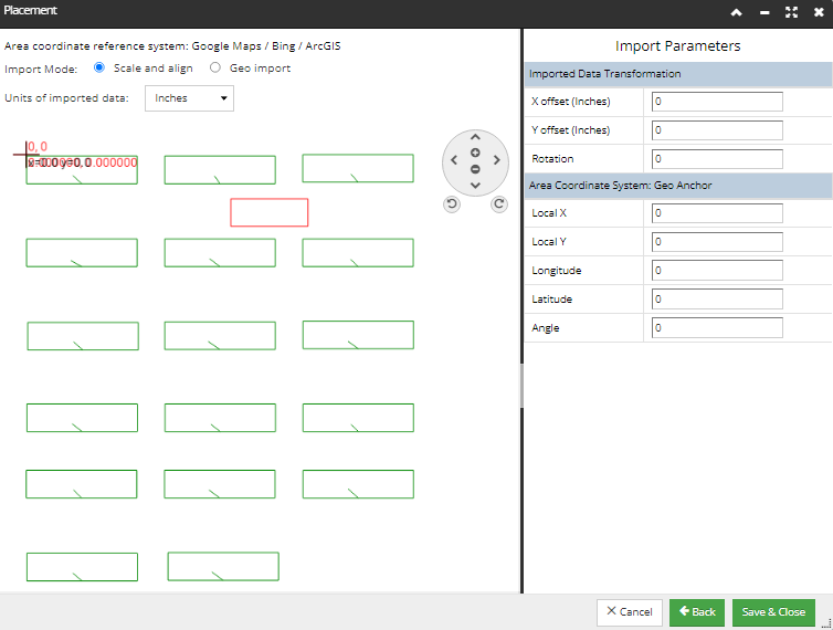
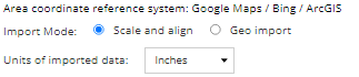
The top of the Placement dialog is dedicated for specifying the CAD Import mode, in respect to the Coordinate systems used both the reference system of the Area and the reference system of the imported data.
First, the Area’s reference coordinate system is displayed. The screenshot example used for this topic has the Google Maps / Bing / ArcGis Coordinate System set for the reference Area:
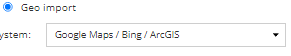
Next, the Import Mode needs to be selected:
Scale and align - if this option is selected, the user needs to select the Units of imported data, which is enabled via a drop-down menu right below it (by default, the units are set to Inches), as seen in the first screenshot image. In Scale and align mode, the numerical panel also shows Rotation, which can be entered directly into this panel field, or the mouse can be used on either a handle or some equivalent mechanism to set the rotation graphically.
In Geo mode, an additional drop-down is displayed, which allows the user to select a custom Coordinate Reference System. As a result, this allows the coordinate reference system to be forced for the imported data. Also, in this mode, the rotation field is still visible but the user can’t set it.
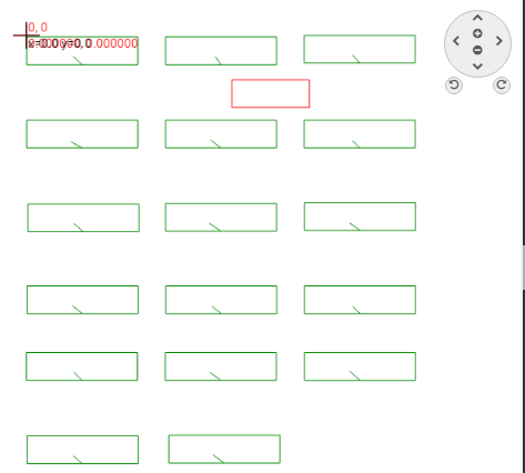
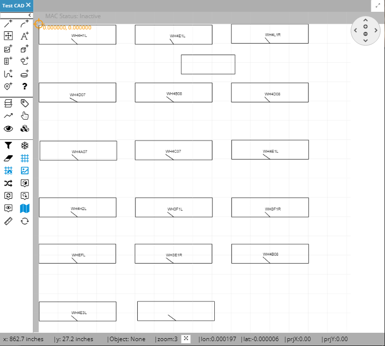
The main portion of the Placement screen displays the selected Area drawing canvas. By default, this Area is zoomed out to the extents of all objects currently defined in the Area, or to ratio that shows the entire imported drawing. The main purpose of the panel is to display the graphical alignment view, where the new data can be positioned with respect to the existing data (assuming there is any existing data).
Set the existing and the newly imported Anchor Points
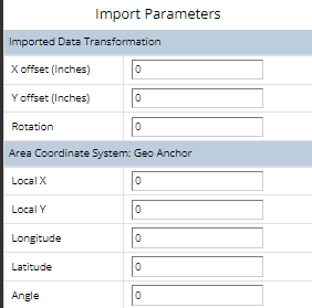
The Import Parameters panel on the right side of the Placement screen displays and allows the user to specify Imported Data Transformation details, such as X / Y offset and Rotation values as well as Geo Anchor Points details, such as the Longitude / Latitude.
Save the CAD Import settings and complete the import
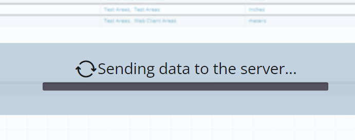
Click on the Save & Close button saves the selected CAD Import parameters and starts the actual drawing import. The progress is indicated with a spinner and the percentage indicating the amount of the import completed. Also, the Save & Close button changes to Saving and is disabled, as well as other buttons at the bottom of the wizard dialog.
Once the import is complete, the wizard dialog is closed and the focus is back to the main application screen. The newly imported drawing file is loaded and displayed in the previously opened Area (canvas).