A Plug is an IRM object that models a real-world cable plug or connector. Plug definitions are based upon a Plug Type which defines how many Connection Points are available within the Plug for terminating Cable media. A Plug Definition is then defined within the Cable to specify the Cable End and Cable media entries that are terminated on which Connection Point within the Plug.
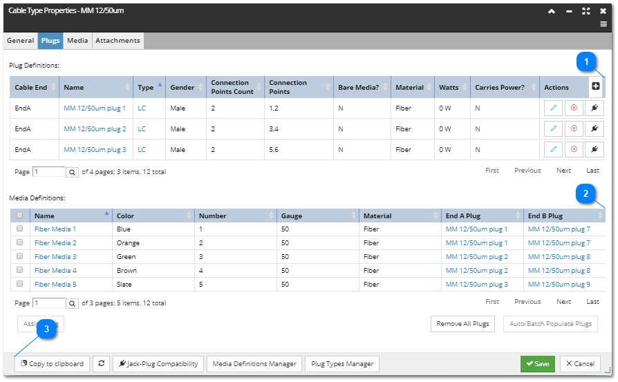
Plug definitions are available through the Plugs tab in the Cable Type dialog. This tab contains two main sections - the Plug section and the Media section. The former lists the set of Plugs defined for this Cable Type, while the latter gives a Media-oriented view of the relationships between Plugs and Media.
The following functions are enabled and explained in the following text and screenshot(s):
This grid lists all Plug Definitions for the selected Cable Type, along with its properties and action buttons. Each row entry is read-only (no inline editing), but is editable through the Edit action button. Selection and de-selection is row-based.
The following fields are displayed for each Plug Definition:
Cable End Indicates which end of the cable this Plug is attached to, can be one of the following values: EndA, EndB, SpliceA, SpliceB
Name of the Plug definition
Type name of the Plug Type this Plug definition contains
Connection Points Count refers to the number of connection points this Plug definition contains
Connection Points is a list of connection points this Plug definition contains (List of consecutive numeric values)
Bare Media? - if false, the Plug is an ordinary Plug that represents a real-world plug; if true, the Plug is a pseudo-Plug that represents the bare end of a media
Material refers to the type of media that the Plug is designed to work with
Watts is the number of watts that can be carried over the Plug
Carries Power? - in case of power-carrying plug is set to true, in case of a non-power-carrying plug is set to false
This grid lists all Media definitions for the selected Cable Type, along with several additional properties. Selection and de-selection is row-based. The grid lists 2 additional columns that indicate if the Media has assigned / connected Plugs and are populated using Add Plugs to End A and Add Plugs to End B buttons located under the grid.
The following fields are displayed for each Media Definition entry:
the first column is reserved for the Checkbox control, which enables quick selection of multiple or all Media entries
Name of the Media entry
Color code assigned to the Media, defined depending on the Media Material
Number of the Media inside the Cable
Gauge represents the diameter / size of the Media
Material of the Media, either Copper or Fiber
End A Plug refers to name of the Plug definition defined for the End A of the Cable
End B Plug refers to name of the Plug definition defined for the End B of the Cable
Bottom of the dialog enables additional dialogs for related object types to be easily accessed:
Jack-Plug Compatibility Editor dialog, which lists all Equipment / Cable compatible pairs, depending on their specified Jack and Plug, enables editing, removing and creating new compatible Jack-Plug compatibility pairs.
Media Definitions Manager dialog, which lists all existing Media Definitions, enables editing, removing and creating new.
Plug Types Manager dialog, which lists all existing Plug Types, enables editing, removing and creating new.