4.3.7.1. Ports, Jacks, Plugs, Connection points
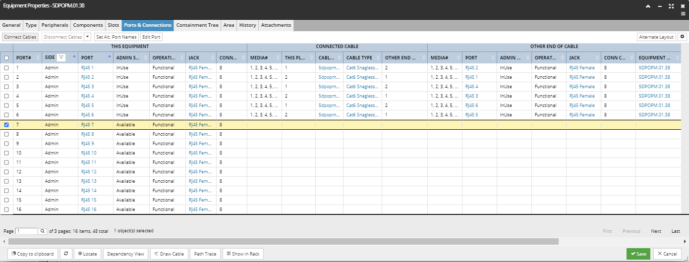
The Ports & Connections tab in the Equipment Properties dialog is the central point in the application to view and manage connections between Equipment and Cables. It lists Equipment Ports in a data grid, along with properties of any connected Cable and Equipment on the other end of that Cable. The tab also enables the user to connect or disconnect Cables for the selected Cable.
Many of the properties listed in the table are objects themselves, all relevant for specifying Equipment - Cable connections:
Port - refers to the physical communication and power interface found on an Equipment
Plug - refers to the physical connector type and associated characteristics of a Cable end
Connection Point - refers to the number of physical connection points each Port contains (on Equipment)
Media - refers to the number of strands or pairs or wires found within a Cable sheath
Those objects have some of their characteristics defined by their underlying Equipment Type or Cable Type object:
Port Definition - holds Type information for a Port, particular to a specific port on a specific Equipment Type
Plug Definition - holds Type information for a Plug, particular to a specific plug on a specific Cable Type
Plug Type - holds Type information common to many Plug Definitions
Click on the highlighted sections for detailed definitions of these objects.
There is a hierarchical relationship between the items above:
Equipment Type
-
-
-
-
Equipment
-
-
Cable Type
-
-
-
Cable
-
-
 "Ports and Connections" gridPorts and Connections grid displays one row for each Port in the current equipment object (the one being edited). It has four column/properties groups:
This Equipment – the fields describing the Port, like the Port Name and Number, Slot Name (if exists), Side (Admin or Term), Jack Type and Connection Count
Connected Cable – the fields describe the Cable that is connected to the Port, like the Media, Plug number, Cable Name and Type, other end Plug number and other end Media
Other end of cable Equipment - the fields describe the equipment at the other end of the Cable, lists the same columns as for the first group, with the additional Equipment Name column
Circuit – lists the circuit(s) that the Port and Cable are associated with
|
 "Connect Cables" buttonThis button is enabled only if one or more Ports which are not currently connected, have been selected.
|
 "Disonnect Cables" buttonThis button allows Cables to be disconnected from Ports. It is enabled when a connected Port is selected, unless that Port that is assigned to a circuit, in which case the button is disabled.
Clicking on the down-arrow next to the button opens a drop-down menu displaying additional quick disconnect options:
|
 Alternate Layout and Field Options buttonsThe Alternate Layout is a toggle button that changes to Normal Layout button when clicked. Clicking on it changes the order of the two Port columns in the grid, in such way that when switched to the Alternate Layout the first Port column is moved to the far right side of the This Equipment group, while the second Port column is moved to the far left side of the Other End of Cable group. Basically, the Alternate Layout enables more convenient view of the Port-Plug mapping.
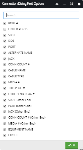
The second (gear) button opens the Connection Dialog Field Options sub-dialog that enables specifying which columns will be displayed in the grid by clicking on the checkbox next to the name of the field / column, as displayed in the screenshot image below:
|
 View button bar - standard button that appears in all Properties dialogs; copies the Equipment object to the Clipboard  - reloads the tab  - locates the Equipment object and centers the view in the Design World  - opens the Dependency View for the selected Equipment object  - opens the Create New Cable dialog that enables to create and place in Design World a new instance of a Cable for the selected Equipment object |
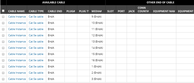
 "Available Cables for Connection" gridThis dialog opens if a non-connected Port (from the main grid) is selected and the Connect Cables button is clicked. It has two versions depending on whether the selected Port(s) have jacks assigned. If the selected port has a jack assigned only cables with plugs that can connect to the Jack will be displayed. If the selected port has no jack assigned then only cables that have no plugs assigned will be listed allowing the user to specify which cable media to connect.
Each row in the grid corresponds to either one Plug or one Media that is available to connect to the current Equipment object.
Note: some Cables may have more than one Plug at each end and only Plugs that are compatible with the selected Port(s) are listed.
The data grid consists of 2 parts:
-
Available Cable – the fields that describe the Cable and its associated Plugs and Media, like the Cable Name, Type and End, Plug and Media number and Plug Type
-
Other end of Cable – lists the basic properties of Equipment that is connected at the other end of the relevant Media in this Cable.
|
 "By Selection" radio buttonThis option is used for manually selecting specific Plugs to connect.
|
 "By parameters" radio buttonThis option is used to specify batch connections of multiple Plugs. Clicking on the By Parameters radio button enables the Parameter input fields that, if set to some values, are applied on selected entries in the grid and select the relevant cable entries.
The following sub-topics cover various cases of using these parameters to make connections.
|
There are two additional sub-dialogs that can open after the Connect button is clicked and will be covered in more detail in the next topic:
-
Plug Mapping – when multiple Plugs are being connected in the same operation, this sub-dialog allows the user to control exactly which Plug is connected to which Port.
-
Media Mapping - when multiple Media are being connected to a Port, this sub-dialog allows the user to control exactly which Media is connected to which connection point in the Port.
For use case scenarios on ports and connections see following topics:
For more details about port definition and management see the following topics: